
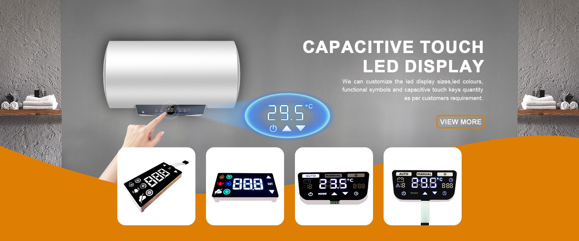
Solar Inverter Displays: Segment LED Readouts Built for Heat, EMI, and Outdoor Duty
Time : Nov 06, 2026 View : 177
A solar inverter is typically located outdoors or in a hot control room and switches at high frequency for long periods of time. Thus, it displays voltage, current, power and fault codes for 10 years or more. In contrast to generic panel meters, the displays of solar inverters have to be readable in direct sunlight, must not be disturbed by switching noise, and have to be operational between -40°C and +85°C. This article describes how segment LED readouts meet these requirements and what an inverter OEM has to watch out for when specifying displays.
Why a Solar Inverter Display Faces Harder Conditions
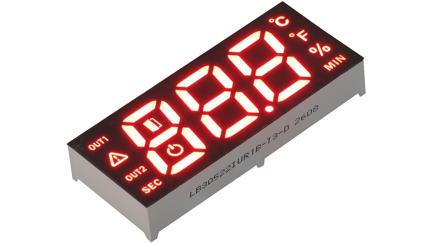
An inverter changes DC power from solar panels into AC power for the electrical grid. The inverter uses high-speed power switching of devices such as IGBTs and MOSFETs, which can produce heat and electrical noise. That same space is occupied by the display of the inverter. Most readouts are located on rooftop units, wall hangers for string inverters, and the outdoor boxes that combine current from multiple arrays.
The displays on your Solar Inverters are not just for show. Service Techs and Installers use them to read DC Voltage, AC Current, Output Wattage, Daily and Lifetime kWh, as well as Fault Codes such as GRID, OVERTEMP, or MPPT failure. Displays that fade or drift can lead to wrong conclusions. Our custom segment LED displays are designed for these kinds of readings: Numeric 7-Segment displays as well as 14- or 16-Segment Alphanumeric displays in the same area.
Heat and Sunlight Inside an Inverter Enclosure
The air in an inverter cabinet is typically higher than room temperature due to the power-conversion losses. For a rooftop unit this air is also above outside temperature and often exposed to the sun at 50°C and more. The segment modules of LIGHTBO are designed for operation between -40°C and +85°C. This allows for use in cold-climate applications as well as in fully sealed cabinets where the temperature inside the cabinet is above outside temperature.
Sunlight is the second test. A display that looks bright on a bench can wash out behind a tinted window at noon. The fix is die-level brightness, not a bigger digit. LIGHTBO’s modules use high-efficiency dies that hold luminous intensity per milliamp across red, green, yellow, blue, white, and amber. A ±60° viewing cone keeps the reading legible from a technician standing to the side, and dark grey or red acrylic filters sharpen contrast through the window.
Holding a Reading Through Switching Noise
High-frequency switching is the part most panel meters never face. Every time a power device turns on or off, it injects noise onto the supply and ground planes, and long cable runs to the display pick up more. When a segment LED is driven by a properly designed constant-current driver, a modest supply variation can show up as a small brightness change. However, the MCU and driver supply still need proper decoupling and noise protection to prevent blank or scrambled readings.
In terms of design, the location of the driver in relation to the display segments is as important as the choice of device. Keep the driver close to the display segments. Keep segment and digit lines as short as possible. The constant-current driver can reduce brightness variation as long as the supply remains within its specified operating range. A common anode display module has the driver configured to sink current from each display segment to turn on the display segment. A common cathode display module has the driver configured to source current to turn on display segments. Both work well, but the display module must match the driver that the board already has.
7-Segment or 14/16-Segment: Matching the Inverter Readout
Most of the information that needs to be displayed by an inverter is of a numeric nature. Information like 230 V, 12.4 A, 3.6 kW, 41.2 kWh can be easily displayed with a 7-segment numeric module. The information is controlled by the microcontroller, either through GPIO circuitry or through a dedicated LED driver.
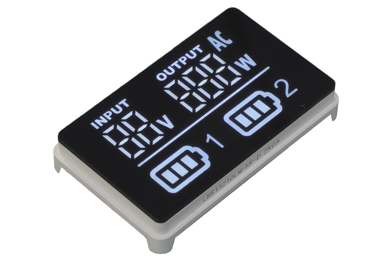
In addition to showing numeric information some screens require text to be displayed on the status line. This text shows the status of a fault, such as FAULT, GRID, ISLAND, MPPT or OVERTEMP and is often followed by units such as °C, Hz or kW. To show A–Z and 0–9 and also common symbols such as /, &, *, etc. above the numeric information of a 7-segment display additional segments are required. These are called diagonal and split vertical segments. A 14-segment LED display has these additional segments. A 16-segment display even splits the top and bottom bars of the 7-segment base again to produce clean letters such as M, W and N. These display types can be used on the same product platform, but changing from 7-segment to 14- or 16-segment may also require changes to the pinout, driver circuitry, PCB footprint, or firmware.
Pinout, Polarity, and Packaging for Inverter Control Boards
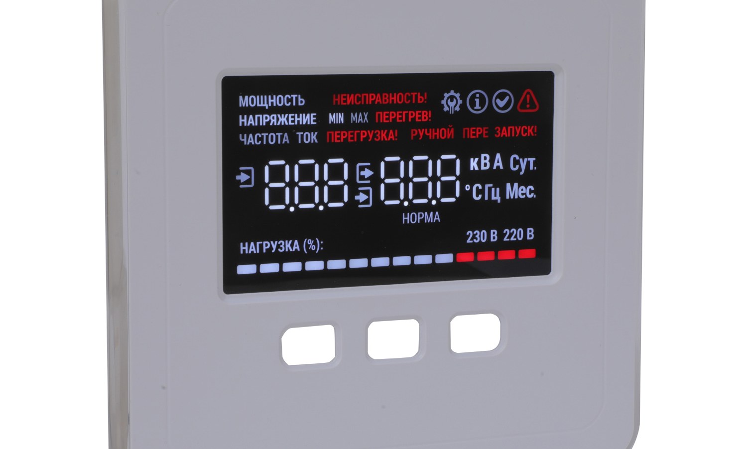
Fit is where inverter projects lose time, and it is rarely the display’s fault. A segment module is a true drop-in only when four things match the existing board: the pinout, the pin pitch, the polarity (common anode or common cathode), and the mechanical envelope — outline, height behind the bezel, and lens window. Miss one and it is not a drop-in.
Through-hole and surface-mount parts are not interchangeable. THT leads pass through plated holes and are soldered on the back; SMD parts sit on surface pads and are reflow-soldered. The footprints differ, and so does the assembly step. Pick the package that matches the line already running, not the one with the better data-sheet number.
A single module with an IC driver (TM1637, HT16K33, MAX7219) can replace up to 16 segment / digit pins with only 2/3 serial pins. An integrated module is an option, not a requirement. Many inverter manufacturers keep the driver on the main board to qualify display and driver as separate parts.
Compliance and Long-Life Testing for Export Inverters
The displays for inverter units that are shipped around the world in complete inverter units must also comply with the same substance restrictions as the rest of the unit. The segment displays from LIGHTBO are manufactured to meet the requirements of RoHS and REACH. The materials and surface finishes have been selected in order to comply with the lists of restricted substances. The certification of the complete inverter, however, is the responsibility of the manufacturer of the inverter.
LIGHTBO defines service life for segment modules to be above 50,000 hours under rated operating conditions. Actual brightness maintenance and color stability depend on drive current, duty cycle, temperature, and operating environment. To detect potential field failures like lifted bond wires due to thermal stress, brightness drift due to incomplete burn-in, corrosion due to humidity as well as aesthetic failures which cannot be detected by a quick visual check, reliability testing can include thermal cycling, burn-in aging, moisture testing as well as automated optical inspection.
Conclusion
In solar inverter displays one has to do more than just show numbers. This display has to remain readable under direct sunlight, it has to be able to be read properly while the inverter is switching and has to last as long as the inverter unit itself. So if a segment LED display meets the temperature range, has a rated service life of 50,000+ hours under specified conditions and can be plugged into the existing control boards of the inverter maker, it can be the basis for a large number of displays.
LIGHTBO supplies 7-segment numeric displays and 14- or 16-segment alphanumeric displays. We can provide displays with custom pinout, custom icons, and displays with custom units for meters and for inverters that need to have a special look. We would like to discuss your inverter display requirements in more detail. We can also provide you with a custom pinout drawing for the display of your choice. You can also order engineering samples.
FAQ
Q: Can a segment LED display stay readable in direct sunlight on a rooftop inverter?
A: Yes. Provided the module is equipped with very high brightness red, green or amber emitters operated within the module’s specified current and duty-cycle limits and a dark grey or red acrylic filter is fitted to the window, very good viewing angles of up to ±60° are achieved. In addition to the red segments listed above for use in indoor or shady locations white and blue segments are available.
Q: What operating temperature range should an inverter display handle?
A: For outdoor/Rooftop Units operating in cold climates, consider a temperature range of -40 °C up to +85 °C. This covers early morning start-up after cold nights as well as enclosed areas where the unit’s internal temperature will be above ambient. LIGHTBO segment modules are rated across the full range and are therefore suitable for use in both indoor string inverters and outdoor cabinets.
Q: Does switching noise inside an inverter affect a segment LED readout?
A: Much less than for other display types. A constant-current driver can reduce brightness variation from moderate supply changes, but adequate power-supply decoupling, grounding, PCB layout, and EMC design are still required to prevent blanking or corrupted readings. Keeping the driver close to the segments and keeping segment lines short will minimize the effect on the reading from high-frequency switching supplies.
Q: Do LIGHTBO inverter displays meet RoHS and REACH for export?
A: Yes. LIGHTBO’s segment modules are made to comply with applicable EU RoHS and REACH requirements. The finished inverter is certified by the inverter manufacturer. This display is just one part of the system.


