
Battery Management System Displays: Segment LED Readouts for Cell Voltage, SOC, and Balancing Status
Time : Nov 12, 2026 View : 114
The battery management system in a lithium-ion battery pack, whether it be in an electric-vehicle, or a rack of energy-storage batteries, supplies information such as cell and pack voltage, state of charge, temperature, as well as balancing information to a local display or host system over the whole life of the pack. The BMS display is typically powered from the same pack that it monitors. In this article we describe how segment LED displays can meet these requirements, and what a BMS OEM should look out for when selecting a display for their application.
What a Battery Management System Display Has to Show
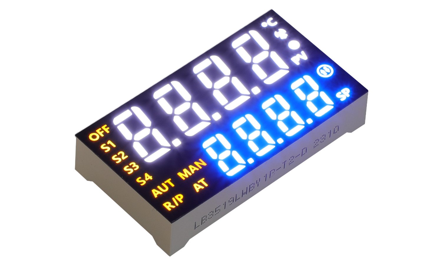
A BMS reads every cell and module in the pack and turns that into a handful of values an operator or service technician can trust. Per-cell voltage in millivolt steps, pack voltage, current, remaining state of charge, cell temperature, and a set of status and fault flags. Most of those values are numeric. Red, green, yellow, blue, white, and amber 7-segment modules render them on a small window set behind a dark filter.
A simple status display using simple digits will not work here, as there are flags like BAL, OV, UV, OT, and short error messages in addition to the numbers to be displayed. A number of segment LED display modules with 14- or 16-segments each can be used to display a much larger set of alphanumeric characters and common symbols than a simple 7-segment display.
Reading Cell Voltage and State of Charge Accurately
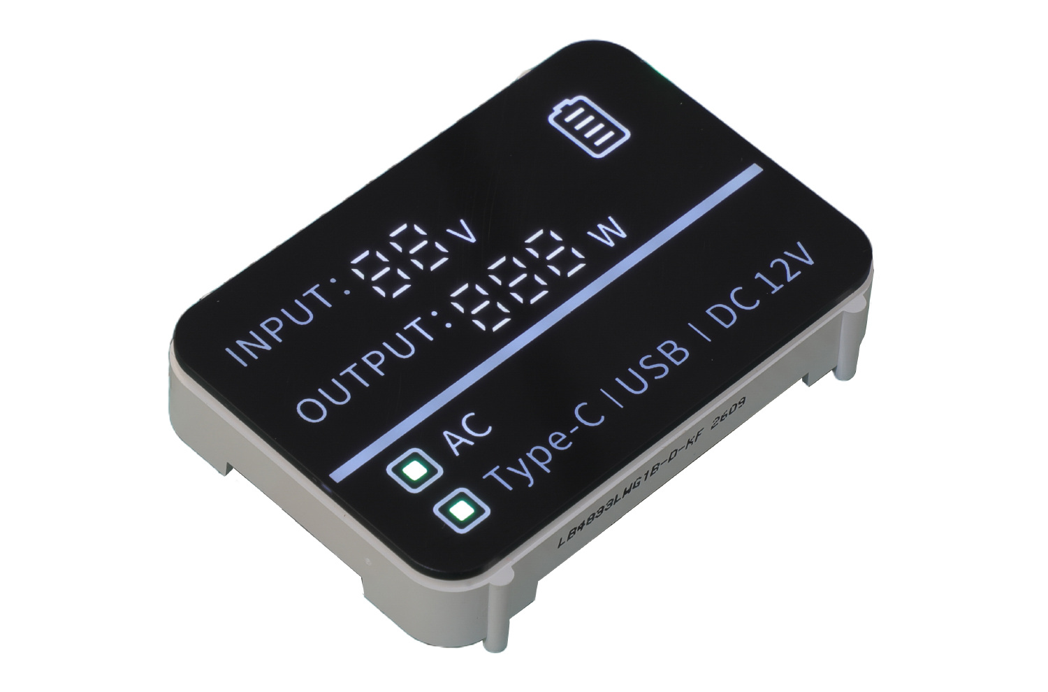
Small differences in cell voltage can be important, depending on the cell chemistry and BMS limits, so the display must show exactly what you have asked it to show and not smooth it out. The state of charge also has to show as a percentage with a consistent display format throughout the pack life.
The life of LED segments is designed to be long but the brightness and lifetime is determined by drive current, duty cycle and ambient temperature. LIGHTBO indicates the service life for selected segment displays tested under specific conditions. The 14-segment display contains the 7-segments of the 7-segment display plus additional diagonal and vertical or split horizontal segments. Letters like M, W and N are shown clearer than with a 7-segment display. For numeric-only values, a 7-segment module is usually sufficient.
Low Power and Standby Drain
This constraint makes BMS different from a mains-powered power meter or inverter. If the display is powered from the monitored battery pack, then the current drawn by the display is debited from the standby current and overall energy budget. The current drawn by Segment LEDs does not include the current to a separate backlight. The actual display current depends on the display module selected, the number of segments displayed, the display drive current and the multiplexing duty cycle.
Determine worst case and average current consumption against the BMS standby-current budget. As usual, the segments should not be driven excessively in order to achieve very bright display values on the workbench. Rather, the drive current and the corresponding duty cycle should be adapted within the specs of the module.
Heat, Vibration, and Switching Noise in the Pack
The air inside a pack can be above ambient temperature near the busbars and contactors. Some LIGHTBO segment display models are rated for operation at temperatures from -40°C up to +85°C. It must be checked whether this rating is available for the selected display part and whether the selected rating corresponds to the actual enclosure temperature and the corresponding thermal conditions.
Thermal cycling due to charging and discharging as well as vibration during transport can cause stress to bond wires and solder joints. Relevant failure risks can be evaluated by thermal cycling as well as by burn-in and moisture testing, while optical inspection can identify visible assembly defects.
In addition to these issues BMS FETs also produce switching noise on the rails. While a constant-current driver tries to keep the display brightness constant despite fluctuating supply voltage, this does not mean that one can disregard good decoupling, a good supply ground, short segment and digit wires. For the chosen display module the already on the board installed driver must be compatible. A common anode display is driven by a sink driver, a common cathode display by a source driver. A wrong polarity can prevent the display from working properly and stress LEDs and driver circuit.
Pinout, Polarity, and Packaging for the BMS Board
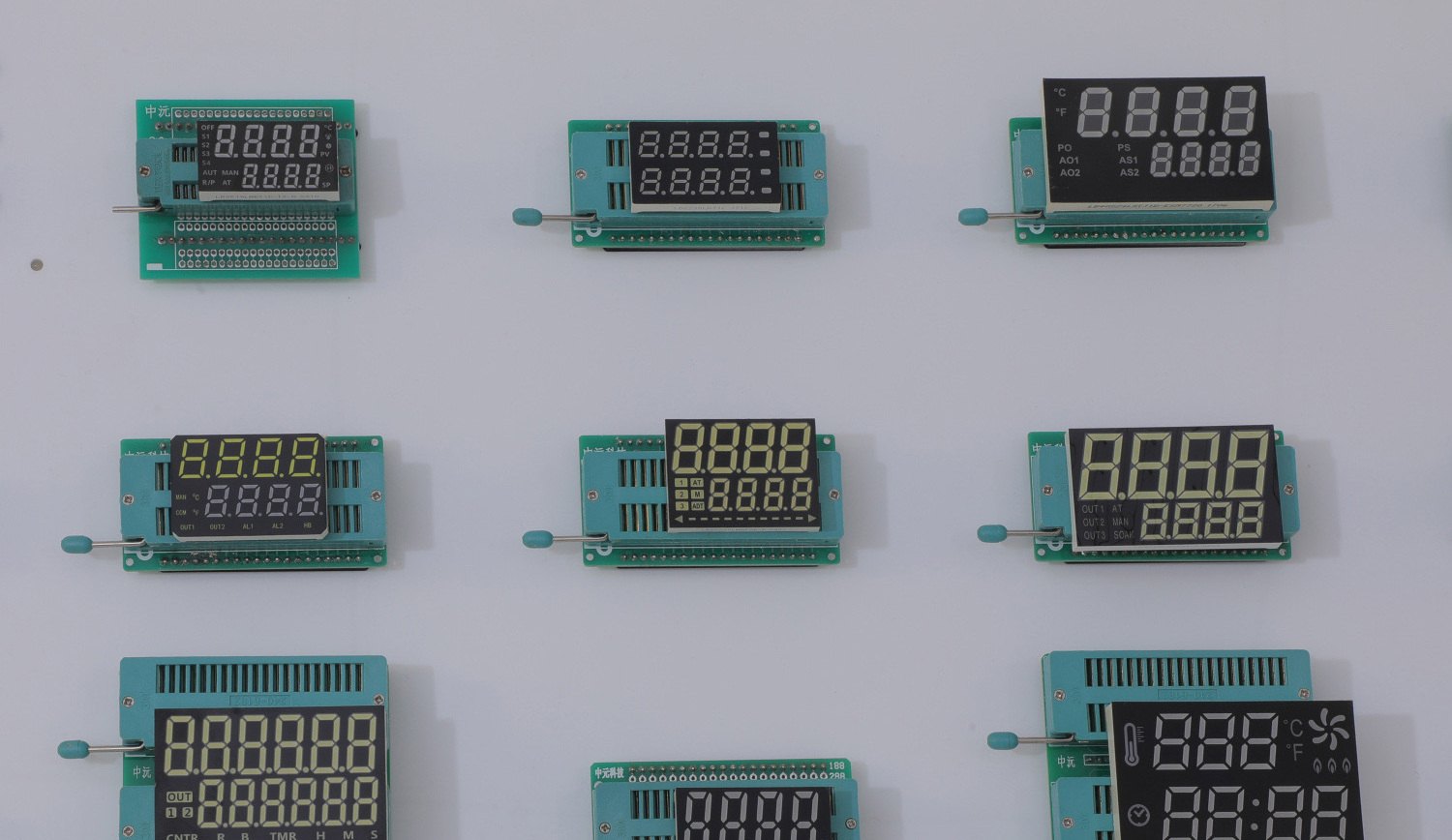
Fit is where BMS programs lose weeks, and it is rarely the display at fault. A segment module is a true drop-in only when four things match the existing board: the pinout, the pin pitch, the polarity (common anode or common cathode), and the mechanical envelope, meaning outline, height behind the window, and lens. Miss one and it is not a drop-in, and the program eats a board spin.
Through-hole components have leads that pass through plated holes in a PCB and are subsequently soldered to the PCB on the backside. Surface-mount components sit on surface pads and are reflow-soldered. The PCB footprints for these two types of components are vastly different. Furthermore, the methods of assembly for through-hole components and surface-mount components are vastly different. Therefore, you must select the component that is already on your preferred line of components rather than the component with the fancier part number on the datasheet.
Silicon vs. Segments. The amount of silicon required to control the segments can be very valuable. A simple driver such as the TM1637, HT16K33 or MAX7219 can control multiple LED segments or even digits as a single display and thus use the MCU’s GPIO only to control the displays and return as many GPIOs as possible for other monitoring and control functions. An integrated module for all parts is possible but the driver usually resides on the main board so that display and driver can be qualified as separate parts.
Compliance and Life to Match the Pack
Component displays delivered within a BMS must comply with the relevant restrictions on substances for the target market/ end product. Component displays offered by LIGHTBO for its segment displays comply with the requirements of RoHS and REACH. The confirmation of the requirements applicable to the end product and the market for this end product is the responsibility of the BMS manufacturer.
Life should match the pack and not an appliance that will fail in a couple of years. Select a display with a suitable rated life under defined conditions. Verify the required brightness in real life with the actual drive current, duty cycle and thermal conditions. Adjust the display choice to match the expected pack life. This helps reduce the risk of display-related failures in the field.
Conclusion
The display of a battery management system shows more than a single value. In order to display the millivolt values of the cells as well as the calculated state-of-charge in percent, some status messages and faults may also need to be displayed. In addition the display must be able to withstand the temperatures and vibrations inside the battery pack and must not consume too much power. A segment LED display can be a suitable solution to show these values within the given temperature range, current budget and within your existing control board.
LIGHTBO produces 7-segment numeric displays as well as 14- or 16-segment alphanumeric displays. These displays can be delivered with a customer specific pinout as well as with customer specific icons. We can also deliver the displays with customer specific units to match the readout of your BMS. We would be happy to discuss your requirements in more detail, to send you a pinout drawing or even send you some engineering samples.
FAQ
Q: Can a 7-segment display carry a BMS cell-voltage and SOC readout?
A: Yes, for the numbers. Cell voltage, pack voltage, and state-of-charge percentage are numeric, so 7-segment digits are enough. The status and fault labels, such as BAL, OV, and temperature units, may need a 14- or 16-segment module or dedicated icons alongside the digits.
Q: How much power does a BMS display draw, and can it stay inside a battery budget?
A: Segment LEDs do not require a separate backlight. The actual display current will depend on the display module chosen, number of segments shown illuminated, display current and multiplexing duty cycle. Calculate worst case current and average current and compare to the standby-current budget for the pack and operate at specified display current and duty cycle.
Q: Will a segment display survive the heat and vibration inside a battery pack?
A: Some LIGHTBO segment modules are rated for operating temperature down to -40°C and up to +85°C. However, the maximum temperature and life must be verified for a specific part. The total unit life is also a function of the drive conditions, thermal conditions, housing and assembly.
Q: Do these displays meet RoHS and REACH for export?
A: LIGHTBO’s segment display products comply with the requirements of RoHS and REACH. However, the BMS manufacturer is responsible for checking the required compliance conditions for the completed system as well as the target market.


