
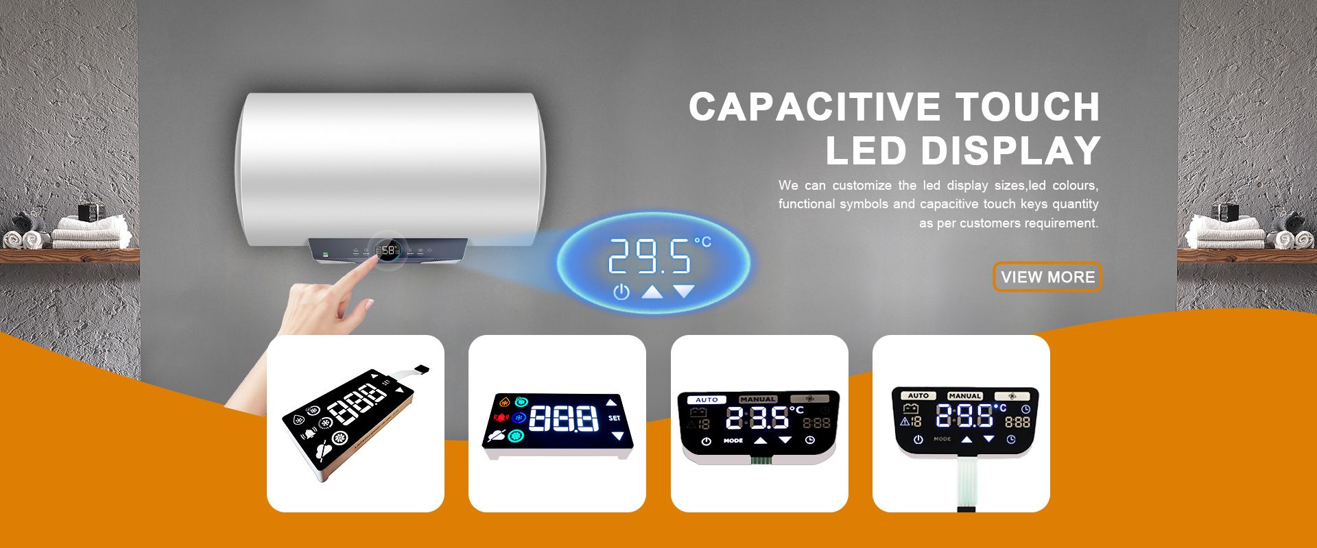
Power Meter Displays: Choosing LED Readouts for Smart Meters and Grid Relays
Time : Nov 05, 2026 View : 177
A smart electricity meter or a grid protection relay has to show the right number for ten or fifteen years in a metal cabinet on a wall. A power meter display must stay readable in a substation at noon, survive a -40 °C winter, and keep the same kWh figure when the supply dips. This guide covers how segment LED displays — 7-segment numeric, 14- and 16-segment alphanumeric — meet those requirements, and what an OEM buyer should check before ordering.
Why Segment LED Readouts Suit Utility Metering
Meters for utility consumption and grid protection relays can be located in two different environments. While indoor DIN-rail mounted meters find space in distribution boards, switchgear cabinets for outdoor applications as well as pole-mounted or substation mounted relays and meter bases are exposed to different influences such as summer heat, frost, humidity, dirt and interference.
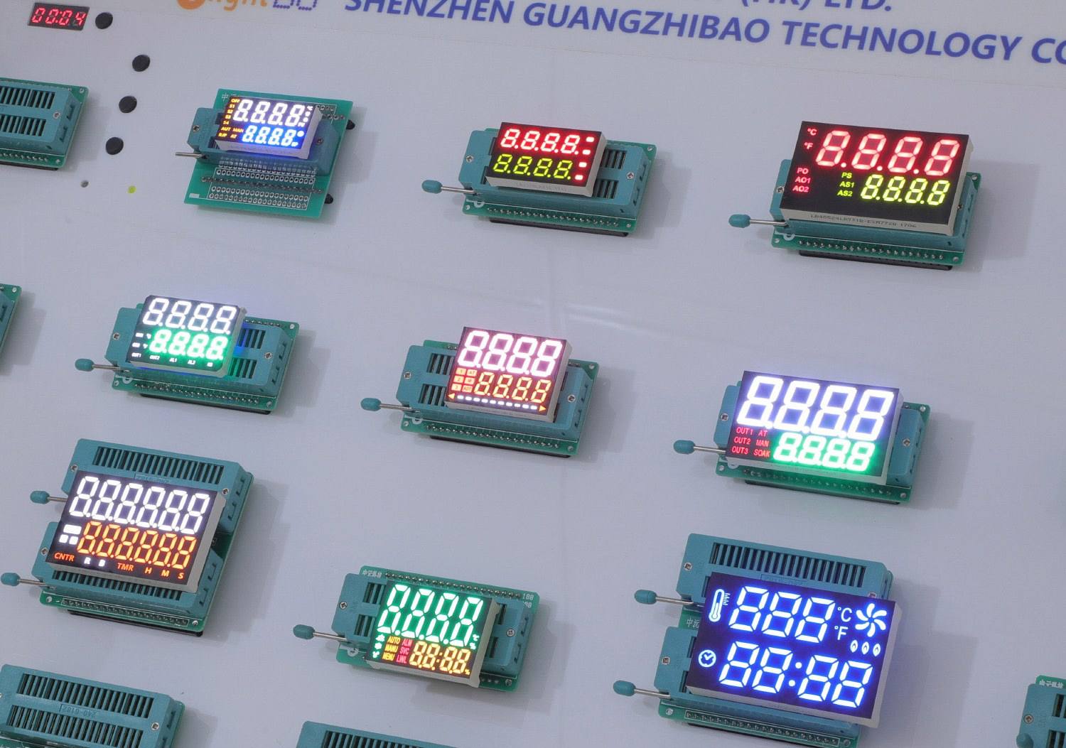
Both types of information can be shown on Segment LED displays. Our custom Segment LED displays are available in 7-segment numeric and 14- or 16-segment alphanumeric architectures. So, a simple panel cutout can be used to show a kWh reading as well as the status of the relays. No re-designing of the panel required.
Reading the Display in Substations and Outdoor Switchgear
Sunlight through a tinted window at high noon is another test of readability. A unit that looks fine on a bench may not read well in such circumstances. In the design of LIGHTBO’s segment modules, we have specified die-level brightness in terms of high efficiency to hold constant the luminous intensity per milliamp for the red, yellow, blue, white and amber wavelengths that meter panels use.
The readout segments are oriented to take advantage of surface-emitting geometry and a viewing cone of ±60° to allow a technician to read the display from a standing position. For displays with dark grey or red acrylic filters, ultra-bright red, yellow-green, and amber display segments provide the highest contrast through the tint.
Temperature Range and Service Life for Decade-Long Deployments
A utility meter typically runs for 10 to 15 years without a service visit so the display has to last for the full period of the meter’s use. Operating temperature and rated life are the two key numbers.
Our segment modules are rated for operation between -40°C and +85°C. So outdoor cabinets can be used in cold climates and also sealed enclosures in cool locations where the temperature inside the enclosure is above ambient. The modules have a rated life of more than 50,000 hours and no burn-in or colour shift of the segments over time. This is the typical failure mode of LCD displays.
How does the meter or relay housing dissipate heat from the LED display? The display operates at 10–20 mA per segment so 6 digit numeric displays run at well under 200 mA total. Within a sealed case this amount of current is fine provided that the case’s thermal design is taken into account. The IP or NEMA rating of the case will depend on the complete meter design, not just the display.
7-Segment, 14/16-Segment, or Alphanumeric: Matching the Readout to the Meter
Not every device needs all the character sets. A simple residential single-phase kWh meter has only one display parameter: the cumulated energy and some status flags. Hence a 7-segment numeric module of 6 or 8 digits in length is the most cost effective solution. It connects directly to the microcontroller and displays all the necessary digits for a utility’s billing system.
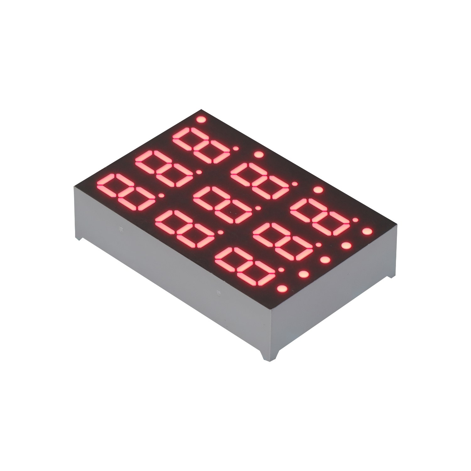
Text that is typically displayed by a three-phase multifunction meter or a grid protection relay includes phase labels (PH-A, PH-B, PH-C), fault codes (TRIP, OVER, ALARM) and measurement units (kV, A, kW). A 14-segment LED display consists of single diagonal segments and split vertical segments in addition to the 7-segment display of the digits. All capital letters A…Z and digits 0…9 as well as the required amount of punctuation can be represented with this display. A 16-segment LED display in addition splits the upper and lower horizontal bars into two halves, which enables clean letters and symbols like °C and Hz to be displayed.
Typically, if your display only contains a few numbers and icons then a 7-segment display is the best choice. However, if a field service engineer or installer needs to read fault messages from your equipment then 14- or 16- segment displays are the way to go. All three types are built using the same tooling so it is easy to change from a purely numeric display to a full alphanumeric display as a single module change.
Pinout, Polarity, and Form Factor for DIN-Rail and Panel Mounting
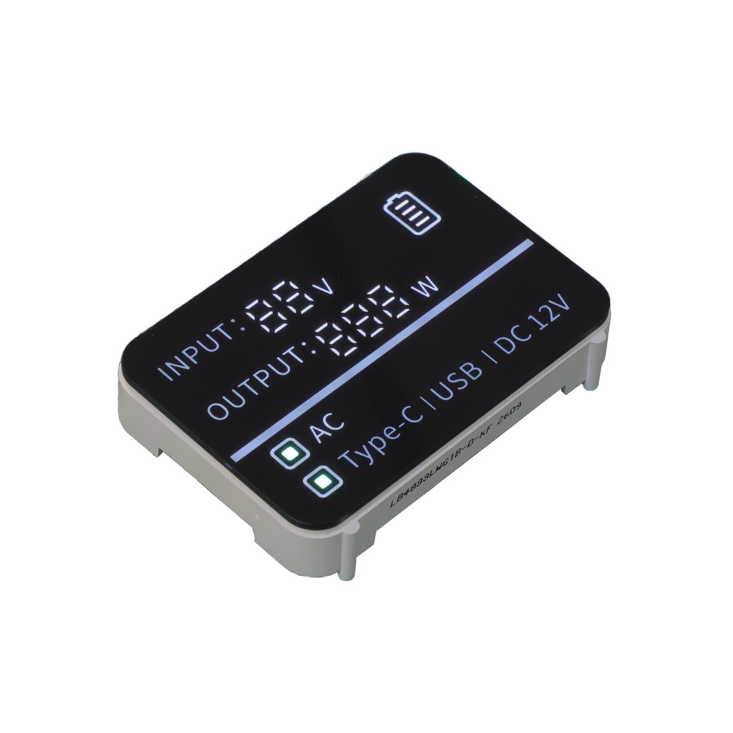
The mechanical and electrical fit is where meter projects actually go wrong, rarely the display’s fault. Three things line up before a segment module is a drop-in replacement for an existing meter PCB: the pinout, the pin pitch, and the polarity (common anode versus common cathode). Add the mechanical envelope — outline, height behind the bezel, lens window — and you have the full set of constraints. For long-lived utility platforms, the pinout match also matters when the original display goes end-of-life (EOL) before the meter: a custom-pinout module built to the original footprint lets the meter maker keep building instead of redesigning the main board.
Anodes of all segments of a common anode module are connected to a common rail. Current is sunk by the driver to ground for each segment that is switched on. For a common cathode module, the driver sources current to segments that are switched on. Mixing both types of modules on one driver results in a completely black display or a display that only lights up when it is supposed to be black. Replacing a module is a matter of mechanics and electrics: the replacement module must have the same polarity as the firmware and the hardware of the driver that is already there, not the other way round.
Through-hole (THT) components have leads which go through holes in the PCB and are then soldered to the PCB’s back side. Surface-mount (SMD) components have leads which are attached to surfaces of the PCB and are then reflow-soldered. The PCB footprints for THT and SMD parts are vastly different and thus require vastly different assembly methods (wave soldering or hand soldering vs. reflow). When choosing parts for a meter platform with an existing assembly line, it is best to choose parts which match the existing line, rather than choosing the best part for the application based on data-sheet numbers.
For designs with limited microcontroller pins, using an integrated module with a built-in driver IC (TM1637, HT16K33 or MAX7219) reduces the connections for up to 16 segment and digit outputs down to 2 or 3 serial output lines. This is an option for smaller, lower-cost meters, but many meter makers choose to run the driver on the main board to allow for qualification of the display and the driver as separate parts.
Sealing, Compliance, and Quality for Export Metering
Utility meters are typically exported. The display panel, being one of the components in a utility meter, also must comply with the destination country’s regulatory requirements. The OEM’s quality system must be able to verify the claims.
LIGHTBO’s segment modules for environmental/ ecological purposes are made to RoHS and REACH requirements. For restricted substances in export countries, suitable materials and surface finishes are selected and LIGHTBO complies with the lists of restricted substances. Market specific certifications, which exceed the list of restricted substances, have to be performed by the meter maker, as the display is only one part of the total system.
In terms of quality, we subject each batch to a series of tests, including thermal cycling, burn-in aging, moisture testing, and automated optical inspection (AOI). The goal of these tests is to replicate the types of failures that one might encounter in the field, including lifted bond wires due to thermal shock, segment brightness shift due to incomplete burn-in, die or PCB corrosion due to humidity, and cosmetic defects that would go undetected were the meter to be inspected by hand at line speed. The meter is intended to last 10-15 years, and this test sequence is what keeps them working when they are recalled for service.
Conclusion
For a utility meter or grid protection relay the display is a long life part, not a commodity item. A segment LED module that matches the temperature characteristics of the meter, retains display intensity throughout its useful life and can be mounted directly to the PCB without modification to satisfy OEM requirements is a component that can be easily designed into a meter.
We supply 7-segment numeric displays as well as 14- or 16-segment alphanumeric displays. All our displays can be supplied with custom pinout, custom icons and custom units for special meters. Please contact us for your meter or relay display. Here you can also request a custom pinout drawing. We can also supply you with engineering samples for testing.
FAQ
Q: Can a segment LED display stay readable under direct sunlight in outdoor switchgear?
A: Yes, the high-brightness red, yellow-green or amber colored die can be operated at the specified 10–20 mA per segment, and a dark grey or red acrylic panel filter can be used for the panel window. For indoor DIN-rail meter applications white and blue segments are available. For outdoor switchgear readouts the longer-wavelength colors are used to provide contrast by means of a tinted lens.
Q: What operating temperature range do utility meter displays need?
A: The safe operating temperature range for outdoor switchgear and pole mounted relays is -40 °C to +85 °C. This ensures that cold winter days and sealed enclosures where the internal temperature is higher than the surrounding air are covered. For DIN-rail meters used indoors, a slightly narrower operating temperature range is acceptable. However, most meter platforms are designed to work within the wider industrial temperature range, thus the same display can be used for indoor and outdoor variants.
Q: Can a custom display match the pinout of an existing meter PCB for a drop-in swap?
A: Yes. LIGHTBO engineers the pinout, pin pitch, and outline to the existing PCB, with the common-anode or common-cathode polarity the firmware expects. The constraint is the full set of mechanical and electrical matches — pinout, pitch, polarity, and envelope — not the pinout alone.
Q: Do LIGHTBO meter displays meet RoHS and REACH for export?
A: The materials and surfaces of LIGHTBO’s segment modules are designed to comply with the restricted substances according to the European legislation on waste, RoHS, and REACH for the EU and other relevant APAC countries. Certification for other markets containing restrictions on substances in addition to those listed in RoHS will require certification of the complete meter by the meter maker as the display is only one component part of the system.


