
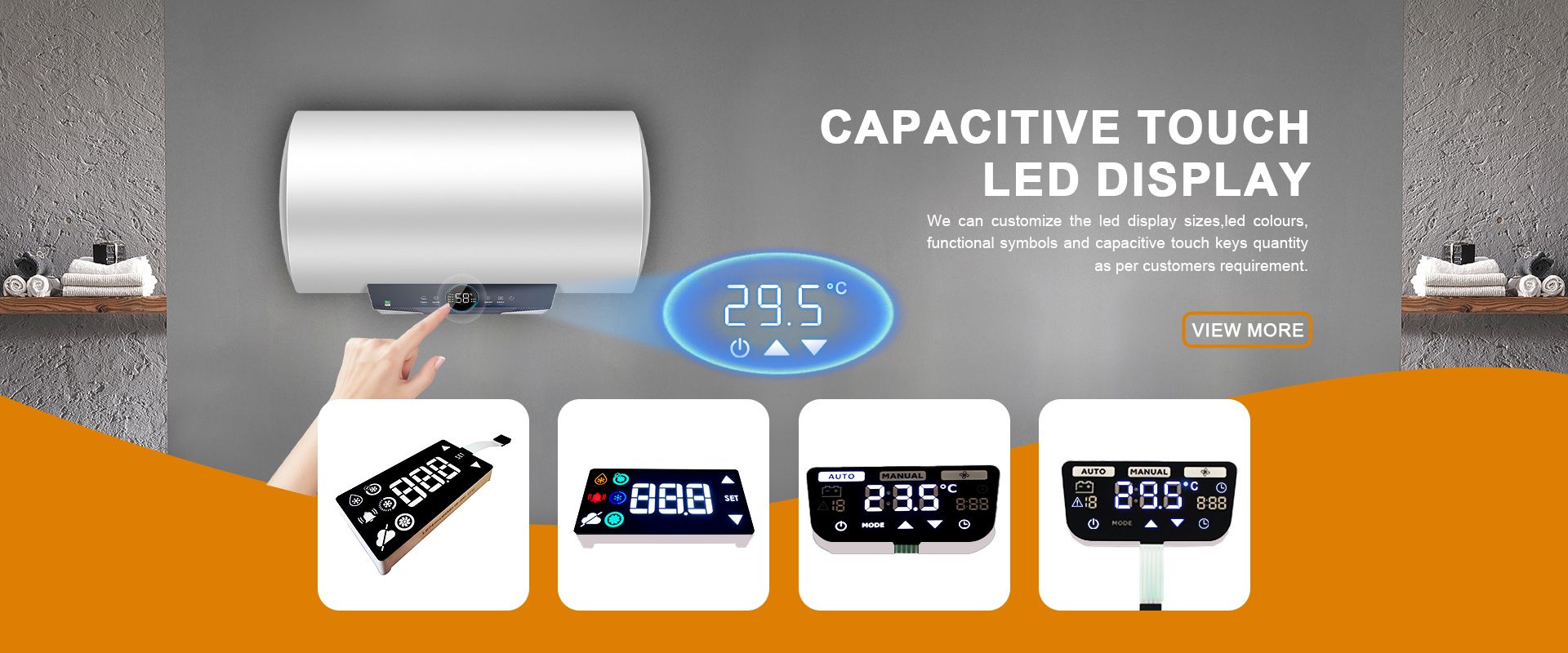
Custom Segment Displays: Adding Icons, Units, and Logo Branding to Your Panel
Time : Oct 30, 2026 View : 253
Readability of the numbers on your panel starts long before someone actually reads them. First they check the status of the machine: is it running? Is there a fault on this panel? Which machine are you looking at? Icons, printed operating values like temperature, pressure, power and revolution, as well as the company logo can be incorporated into a custom segment display for your OEM panel. LIGHTBO manufactures custom segment displays. The artwork is part of the design and not an extra afterwards.
Typical seven-segment displays are restricted to the quick representation of numbers and a few letters. For more detailed fault messages, however, more than what can be represented by 14-segment or 16-segment displays with alphanumeric characters has to be displayed. The custom icon segments make up for the fact that no font is available to draw special symbols. Hence there is a great difference between a panel that has to be decoded from a manual and a panel that can be immediately read.
What a Panel Communicates Before the Numbers
Most control panels carry three layers of information. Live values: speed, frequency, temperature, pressure. Status: run, stop, local, remote, fault. And identity: whose product this is, and which unit the value refers to. Digits serve the first layer. Status and identity need icons, labels, and overlays.
Many panels require a second display to show the icon row once the numeric row is complete. The early planning of the artwork to remain on one module is crucial in order to keep a check on the overall mechanical envelope and prevent it from growing too late in the project.
Custom Icons, Arrows, and Bar Graphs
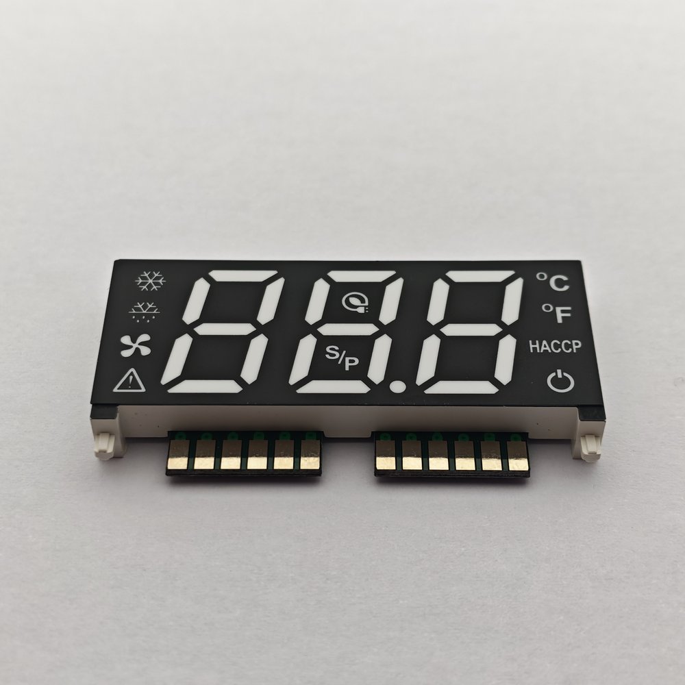
Icons on a segment display are not drawn from a character font. Rather, icons are dedicated graphic segments – custom made segment shapes drawn directly on the module with the drawing tools provided. A simple example of such an icon could be a snowflake, a fan blade, a battery or even an alarm triangle. Each of these icons is a separate segment group and can be driven independently of the digits.
Arrows, which are used to indicate rotation, up and down on a set-point editor, are also worth a mention. On a pump panel arrows are used to indicate the direction of flow. This is much faster to read than the letter D or R and is language independent.
Bar graphs are also found along the margin and can represent discrete values in rough order. Multi-color segments can represent both level and limit. For example, red over the trip point, green below the trip point.
Units and Labels: °C, Bar, kW, RPM on One Display
There are two ways to place a unit next to a number. These two ways are not interchangeable.
Use “°C”, “Bar”, “kW” and “RPM” as the unit name by spelling out the word using alphanumeric characters. Note that the unit name changes with the parameter in the different set-point modes of the controller. This use of digit area for the unit name instead of displaying numbers and using the area for the letters instead has a cost.
A dedicated unit segment can display a fixed unit symbol, such as °C, alongside the numeric digits. This section is always ON at the same relative brightness as the rest of the display. From a driver’s perspective there is no additional code required to display a dedicated unit section other than that required to display the section. Dedicated unit sections are generally found on meters and appliances that are measuring something that is not changing.
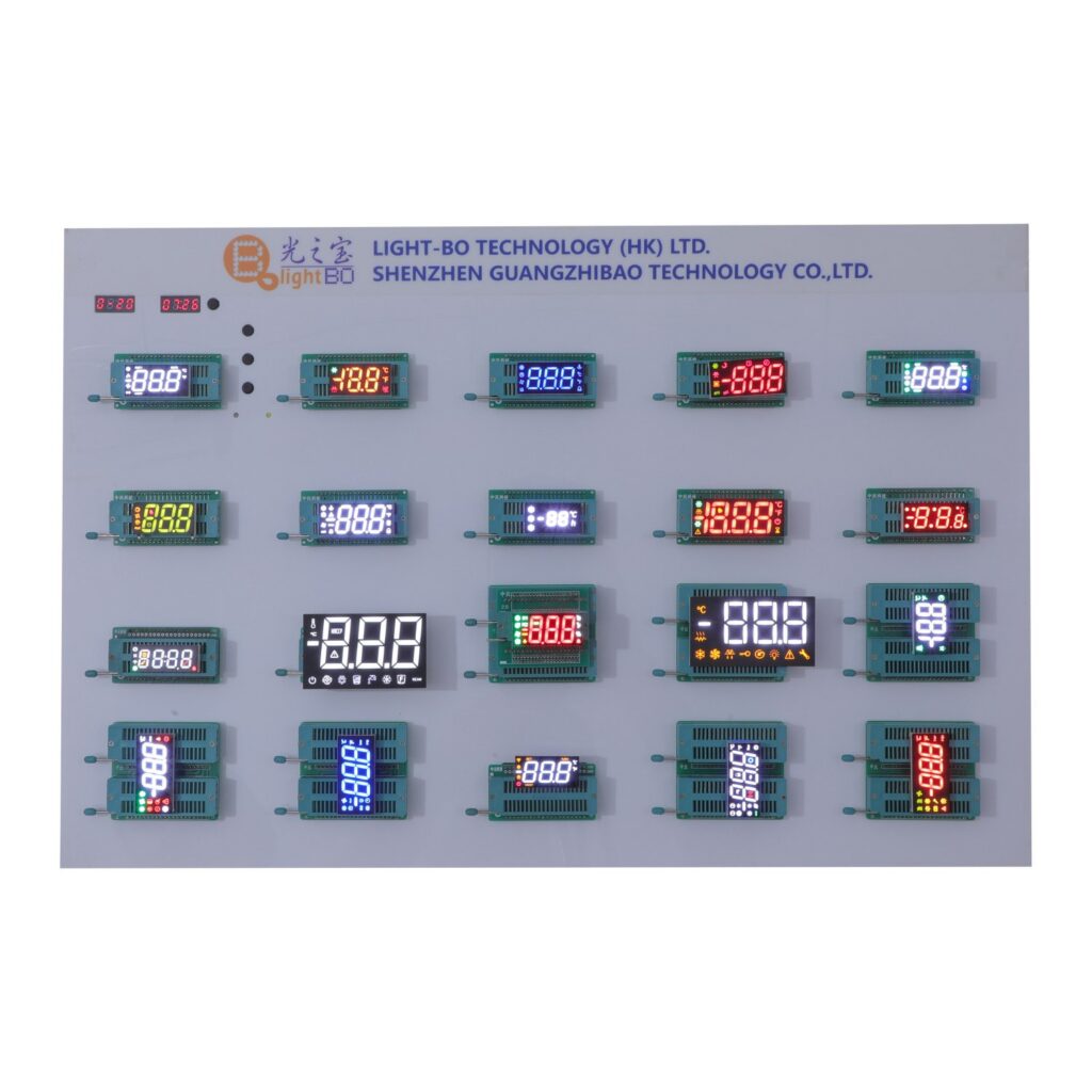
This is similar to the short alphanumeric labels that are used as status indicators for the running modes, for the outputs, for the communications etc. An example for this could be MAN/AUTO, OUT1/AL1, COM:. These short rows of labels, mixing them up with fields of numbers, are very common on temperature controllers and on drive panels of that kind.
Adding Your Logo and Panel Overlay
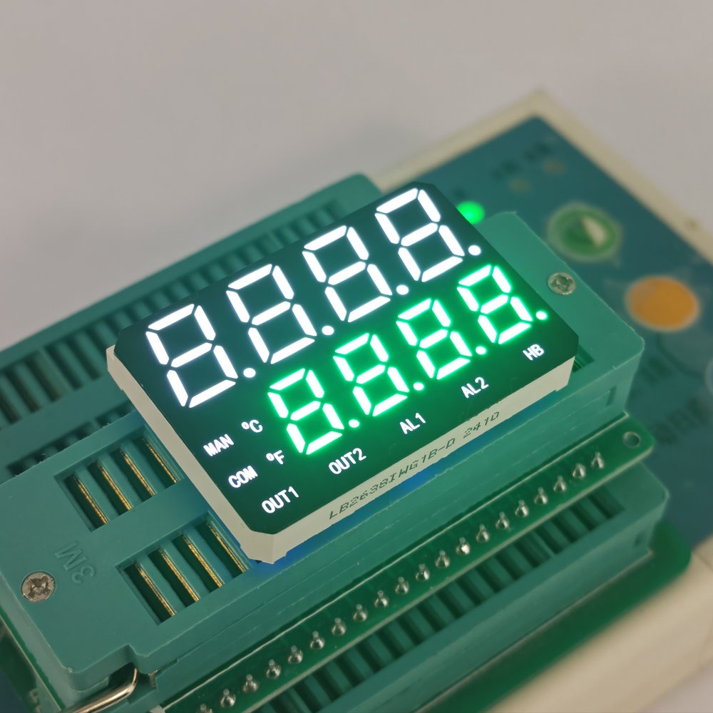
Brand recognition on an LED display module is generally a print on the front side of the display panel outside of the segment map. This would be printed next to the segment windows as identified by the Industrial Designer. The panel base color is typically a dark black or grey color and the segment film is a matching color to the base color of the display panel so that the unlit module still looks a complete finished product.
For low cost retrofits, the replacement display is fitted into the existing cabinet. The new display must have the same number of digits of the same height, go through the same cutouts in the display window and have the same electrical connections as the original display part. The overlay is then re-printed to make the new part look original.
The color of the overlay is chosen to enhance the legibility of the display’s tint and the space between the segments of the digits. Standard colors for the display’s segments are red, green, amber, blue and white. Typically red is used for alarms and green for normal operation. The operator can thus read the status of the display before he reads the value. Surface-emitting segments of the display have readable values until about ±60° off-axis. This is critical when the panel is mounted to the back of a cabinet.

Making a Custom Segment Display: From Panel Drawing to Working Sample
Custom artwork is normal for segment display projects. We create CAD drawings and a working sample of your panel, signal list and icon sketch. We also provide free engineering samples for testing before we start production. This is by far the cheapest point at which you will find out that an icon does not read at arm’s length.
We would test returned modules in an identical fashion to new modules i.e. thermal cycling, burn-in aging etc. on our production line and checked using our AOI system. We specify standard modules to have an operating temperature range of -40°C to +85°C. Drive current per segment is 10–20 mA. We specify standard modules to last over 50,000 hours. All custom segment displays are shipped with confirmation that the overlay and segment film materials have been checked against the applicable RoHS and REACH requirements.
Similar to displays showing just numbers, displays showing many icons greatly benefit from integrated drivers for displays driven by TM1637, HT16K33 and MAX7219. Their integrated drivers take care of things like scan-limit and brightness so the MCU only has to deal with 2-3 control pins.
Conclusion
Customizing the display of a segment display with icons, units and a logo is more than just coloring and graphics. Status and identity information are integrated into the numbers of the display module itself. Thus, a second display for the panel is not required. Typical engineering questions for this are: Which units are to be printed as constant, which icons are required, what does the overlay color add for contrast, and does the driver have enough segments for this.
A simple panel layout drawing is a good starting point for us. From this one panel layout drawing and associated signal list we create a working sample consisting of a segment map, the individual icon segments and a panel overlay. Contact LIGHTBO with your panel drawing and signal list.
FAQ
Q: Can a seven-segment display show icons or units?
A: Typical seven-segment displays are designed to display numbers and a few letters. To display arbitrary icons, you would add dedicated graphic segments to a custom module to show the required symbols that the corresponding off-the-shelf seven-segment display does not have. Standard seven-segment displays are purely numeric.
Q: Which units can appear on a custom segment display?
A: Artwork for units like °C, Bar, kW and RPM can be handled as fixed printed labels or dedicated display segments. Whether a unit is printed as text or as a segment depends on whether you are displaying one constant parameter or whether you are switching between different parameters.
Q: Does adding icons increase pin count and driver complexity?
A: This increases the raw number of segments of course. However, the integrated driver modules for the display such as the TM1637, HT16K33 and MAX7219 take care of scanning and the brightness in local logic. Thus the number of pins on the MCU side only increases to 2-3. The current per segment is as usual in the order of 10-20 mA.
Q: Can a custom overlay match an existing panel for a retrofit?
A: Within the mechanical constraints of the new display, the digit height, cutouts and mounting aperture will be the same as for the original display. We can also reassign the pinout to match the current board. An engineering sample can be sent for verification purposes before production.


