
How to Choose LED Displays for VFDs, Soft Starters, and Motor Drives
Time : Oct 29, 2026 View : 244
A simple segment display showing clean numeric values for VFDs, soft starters and motor control panels such as speed, torque, frequency etc. plus plain text fault messages as opposed to error codes is usually all that is required. The rest is engineering fit. Segment count, driver integration, pinout and environmental rating must all match up with the rest of the engineering in the panel. It must fit in the space provided.
LIGHTBO produces individual customized segment LED displays for the motor control units and automation systems used in factories. The following figures illustrate the area covered by the modules that LIGHTBO produces for these applications. They illustrate the operating range, drive current, viewing angle and housing dimensions.
What Motor Drive Panels Ask of a Display
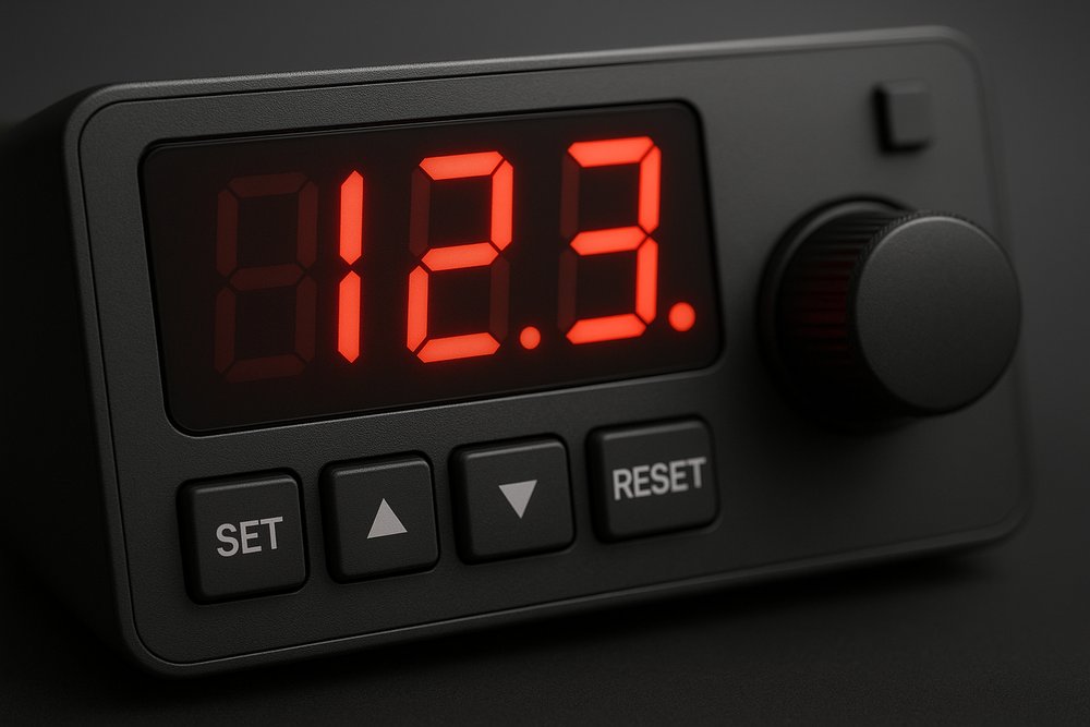
A typical installation for a motor drive panel is within a shop floor cabinet, with contactors and large motors mounted to the cabinet’s mounting plate. Temperature can vary greatly from cold shop start on a Monday morning through to hot afternoons of continuous running. Arm’s length viewing at a typical angle to the display face is typical. Occasionally the display is viewed through a scratched polycarbonate window.
Three kinds of information have to come through. Live values: speed in RPM, output frequency in Hz, load current in amps. Status: rotation direction, run or stop, local or remote. And the fault channel — overcurrent, overvoltage, overheat — the moment the drive trips and the line stops.
A mostly numeric display is suitable for live data but not for status and fault information.
Segment Architecture for a VFD Display: Numeric, Alphanumeric, or Both
7-segment digits display the numbers 0-9 and a few pseudo letters. For a drive displaying only speed and frequency, these are the obvious choice: bright, easy to multiplex and inexpensive as individual digits. Many VFD keypads consist of just such digits.
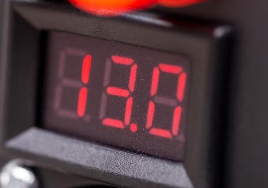
There are a number of limitations to using 7-segment displays to show fault information. First, 7-segment displays cannot display arbitrary text. For example, if a drive were to trip for some reason, the operator would read the number displayed on the 7-segment display for that drive and refer to the drive’s manual to see if the problem is with the drive, wiring or load. In the meantime, a 14-segment or 16-segment alphanumeric display could have displayed the words OVERHEAT or UNDER-VOLT to immediately indicate the problem to the technician.
14- and 16-segment displays can display most alphanumeric characters and symbols. The set of characters that can be displayed depends on the configuration of the display segments and the software that drives the display. The 16-segment display has the top and bottom two horizontal segments divided into two, thus making uppercase characters more symmetrical than on a 14-segment display. On displays with values and labels for power, current etc. such as Hz, kW, RPM, Bar, °C, the extra segments are very usefully employed.
A typical motor control panel has a mixed layout of large numerals for running speed and a small alphanumeric display for the parameter text. Run, stop and revolution indicators are displayed as custom icons. Other indicators like arrows, alarms and multicolored bar graphs are also displayed on this screen as required. Custom units are displayed for specific parameters.

Driving the Display: Integrated Modules vs MCU GPIO
Many MCU I/O lines are required to directly drive a multi-digit display. Multiplexing of the segment connections of the individual digits is the common practice. Using a dedicated display driver can reduce MCU I/O requirements and the software workload associated with display scanning.
An integrated LED display module includes the functions to drive the LEDs within the display module. The Driver ICs TM1637, HT16K33 and MAX7219 can be used to control the display scanning as well as to adjust the brightness of the LEDs. TM1637 is controlled via a proprietary 2 wire interface, the HT16K33 via the I²C interface and the MAX7219 via a serial interface. The host MCU sends display data to the driver IC, which handles display scanning and brightness control as long as the supply remains within the specified operating range.
Make sure that you connect the correct polarity to the ends of the display. A common anode display is driven by a driver that sinks current for each display segment while a common cathode display is driven by a driver that sources current for each display segment. A replacement display therefore must have the same polarity as your currently used driver circuit.
There are also electrical noise advantages. The high frequency switching of high current in a VFD can generate significant amounts of noise within a cabinet. Keeping the high frequency current traces short by placing the driver close to the display segments means that the display-drive traces are short. This can help reduce susceptibility to switching noise and reduce unwanted emissions.
Mechanical and Environmental Fit
The selection of electrical parts for a display module typically precedes the sizing of the mechanical envelope to determine if the module will be a true drop-in part or if a total redesign is required. A drop-in part must match the mechanical dimensions and the pinout of the original part, including the polarity, the voltage and current, as well as the driver. A mechanical mismatch will prevent installation, an electrical mismatch will cause wrong operation or no display at all. A pinout mismatch will result in missing or wrong segments, dark digits or other problems with the display.
Packaging is designed for the assembly line. THT display packages use through-hole PCB mounting, while SMD display packages use surface-mount pads and are commonly assembled using SMT processes. Changing the type of packaging on a part generally requires changes to the PCB and to the assembly processes as well.
The environment. Here we discuss temperature and vibration of a motor drive cabinet. The display temperature rating must match the environment in which the cabinet is located. LIGHTBO offers display models rated for operating temperatures from -40°C up to +85°C. The display segments are solid-state and do not have a glass substrate which could break due to vibration. The service life of a display is strongly dependent on the type of LEDs used, the drive current, the duty cycle, the temperature and the design of the product. Displays, which are used outside or in washdown areas, have to be sealed to the environment and must have the correct size to fit into the application’s cabinet or enclosure. The environmental protection level applies to the finished sealed assembly, not to the bare display alone. Displays can also be customized to fit the required panel or enclosure dimensions.
A list of restricted items for exported goods has to be observed. Our LIGHTBO modules are manufactured with all applicable provisions of RoHS and REACH in mind. Appropriate tests for quality and reliability are performed according to product and customer requirements.
Custom Capabilities at LIGHTBO
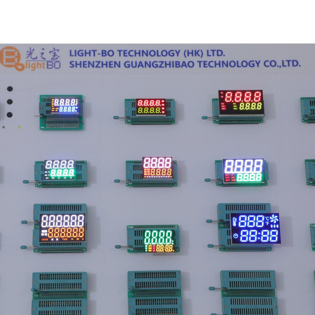
LIGHTBO manufacture custom segment displays used in motor control and factory automation. We produce 7-segment numeric displays as well as 14- and 16-segment alphanumeric displays, complete with driving IC placed in a module. Our in-house design team can work from your schematic to produce CAD drawings and working samples. We can also adjust most parameters to fit within the bounds of the panel on which the display is to be mounted. A simple panel outline and signal list is all we need to get started.
Conclusion
When selecting a VFD display for a motor drive there are a number of key points to consider. Can the display show text or will it be running with digits only? Does the display need to be driven directly by the MCU, or can it use an integrated driver? Define the mechanical envelope and verify the display polarity. After that check the module against the actual operating temperature and any vibration that may exist in the cabinet, not just nominal figures from the datasheet. If these 4 simple points are satisfied then the display should not be a problem in the panel.
We can also design and build a custom segment display for you. We can create the pinouts to match your board, the icons and units you require for your parameters, and pick a design that is suitable for the real environmental conditions of your drive. Contact LIGHTBO with your panel drawing and signal list.
FAQ
Q: Can a VFD display show fault text, or only numbers?
A: Yes, both can be designed. A 7-segment display typically shows numbers and some letters which are defined by the code for possible error messages. 14- or 16-segment displays are alphanumeric, meaning many letters, numbers and symbols can be displayed. The set of characters that can be displayed depends on the segment mapping and on the software of the display driver.
Q: Will an integrated driver module hold up inside a VFD cabinet?
A: The use of a driver IC on the module substrate keeps the display-drive traces short and thus less susceptible to switching noise. However, the module’s temperature rating must match the cabinet environment. Noise immunity, vibration and supply variation are to be checked in the system design separately.
Q: Can the display match the pinout of an existing drive panel?
A: Yes. A true drop-in replacement will have to match the original part’s pinout, pin pitch, polarity, mechanical dimensions, voltage and driver requirements. A custom pinout layout can be designed from the original part’s datasheet or from a sample part, enabling it to be plugged into the board without requiring a mainboard redesign, as long as all electrical and mechanical conditions are met. Conditions such as pin center line spacing, right angle pins and header footprint can also be met.
Q: What temperature range and lifetime should I expect?
A: The required temperature range and the lifetime of your display will largely depend on your design for the specific application. LIGHTBO offers display models rated for operating temperatures from -40°C up to +85°C. The segment current and the expected lifetime will also depend on the display design and the specific conditions it is exposed to. This information can be found in the specification of the products. Modules for outdoor use or washdown panels can be sealed as part of the completed assembly.


