Custom LED Display Pinout: A Drop-In Replacement Guide
Time : Oct 23, 2026 View : 536
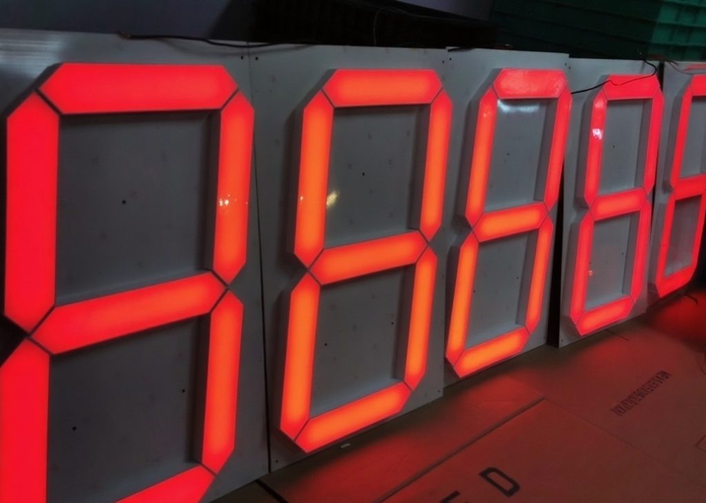
While most replacement projects fail at the interface with the front panel, three parameters determine whether a new module can be plugged into an existing board: the pinout, the pin pitch and the drive polarity. The mechanical envelope and the operating conditions of the electrical signals have to match as well. With custom LED display pinouts, most of the risk sits in the display design itself. At LIGHTBO we design custom segment display modules around the mechanical footprint of our customers’ existing boards. Hence it is often possible to replace a legacy numeric or alphanumeric readout on the control board without designing a completely new control board.
Why the Pinout Comes First
With long-life equipment, the problem is often not a failed display but an obsolete one that can no longer be sourced.
That old controller may still function perfectly but a multi-digit display module for the front panel of that controller may be long discontinued. Copying the external dimensions of the mechanical part is easy enough. But matching the connectors for the electrical interface is not as simple as it seems. Two displays of 0.56 inch height can look identical from the front, but they can have a completely different number of pins, or even different pin spacing and polarity.
Pinout, Pitch, and Polarity
First, establish the pinout, pitch, and polarity. Later, the brightness and color can be set as desired. The digit height is flexible as well. In contrast, the mechanical envelope of the new module must still fit within the old’s cut-out.
The pinout specifies which pin connects to which segment, digit and common for the display. The pitch is the space between the pins and this must match the existing holes or solder points on the PCB. The polarity of the display specifies the direction of current flow, either common anode or common cathode.
A single swapped pin typically manifests as one dead segment or a never lighting digit. It is easy to mistake this for a driver fault and start troubleshooting the driver circuit instead of checking the pinout.
Polarity and Driver Compatibility
Most replacement projects are ruined by polarity issues. A common anode LED display has a driver that sinks current to the segments one by one. A common cathode display has a driver that sources current to the segments one by one. Typically both versions of a custom segment display module are available. The replacement should therefore match the polarity expected by the existing driver.
The driver IC matters as well. Devices such as the TM1637, HT16K33, and MAX7219 use different output arrangements and drive methods. A replacement display needs to be electrically compatible with the driver already used on the board. If that compatibility is maintained, the existing driver can usually remain in place.
Documenting the Existing Footprint
Take pictures of the old display’s front panel before you start to specify for replacement. A part number by itself is not enough to ensure proper specification for replacement.
Measuring Pins, Pitch, and Mounting
Create a pin-by-pin map of the old module. Count the pins and note the spacing between them and the rows. Also note where the common pins are located. Take note of the outer dimensions of the module and any lugs for mounting. Although a module can be completely electrically equivalent to another, it can still foul the cut-out from the panel. Check for continuity between the pins to establish which pin connects to which segment. The silkscreen on the PCB may have worn away in places.
LIGHTBO custom segment displays can be specified for requirements such as -40°C to +85°C operation, 10-20mA per segment, and service-life requirements above 50,000 hours. Check the required parameters for your application: temperature, current, duty cycle and service life. A module that fits today may still fail in the field.
Through-Hole or SMD: Matching the Assembly Line
Package style has to match the production line, not just the board. Through-hole parts suit older assemblies and heavy-duty manual soldering. Surface-mount parts run on automated SMT lines.
Swap a through-hole part for an SMD part and the line changes with it: new stencils, a new reflow profile. Keep the original package and the process stays as it is.
Custom LED Display Pinout Engineering for a Drop-In Part
A true drop-in replacement is often a custom part, even when it looks like a standard off-the-shelf display.
Mapping a Legacy Pinout to a New Module
We use the old datasheet as a starting point. If the datasheet is not available for some reason, we test a sample instead. The segments, digits and common lines are then mapped to the new pin layout. The new layout is checked in the CAD drawings before the tooling is cut.
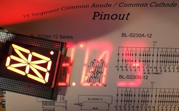
Small differences can be absorbed when replacing a 14-segment alphanumeric LED display. A new display can be of the same size and still have cleaner segment geometry. So the panel looks the same but the characters look better.
Right-Angle Pins, Custom Headers, and Spacing
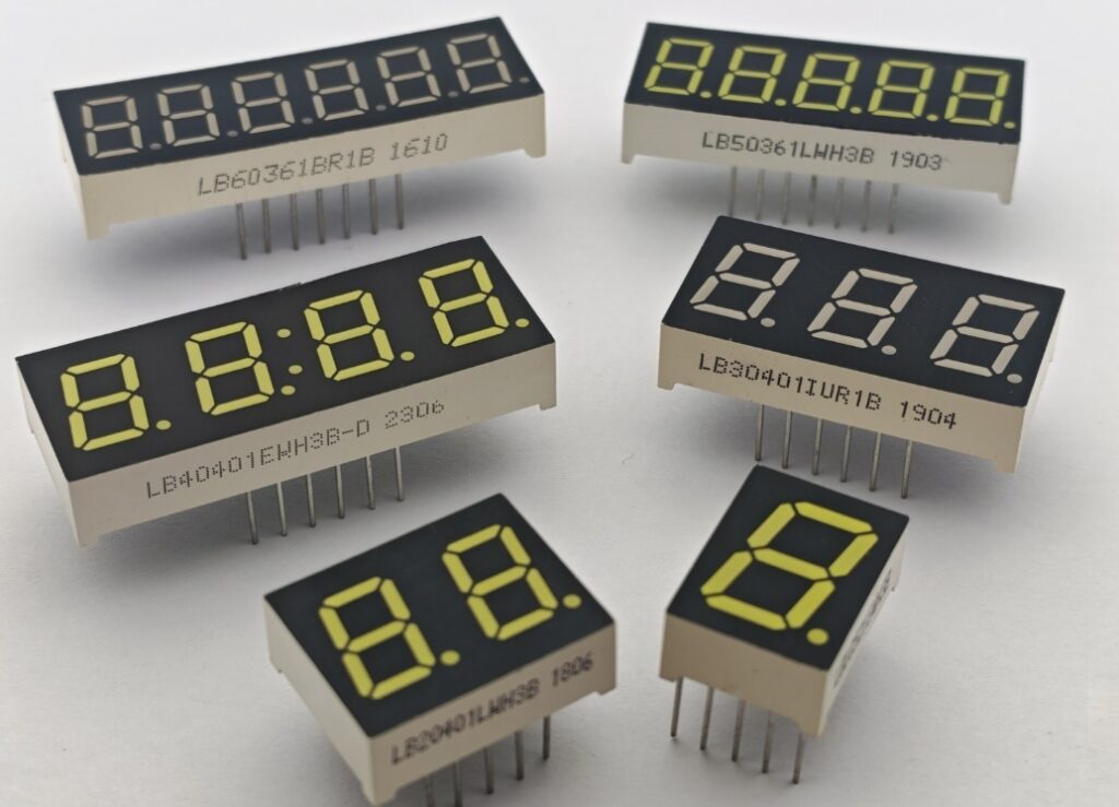
Whether the replacement module sits correctly on the board is largely a mechanical issue. Providing right-angle pins, a custom header footprint, or even odd-sized spacing between pins for example are all standard requests in order to use an existing board as opposed to re-designing one from scratch.
A module can be electrically perfect and still be off by a fraction of a millimeter in height or have the connector land a few millimeters off. That is not a drop-in part. Custom tooling closes that kind of gap.
Where Drop-In Displays Pay Off Most
Replacement work clusters in equipment built to run for a decade or more. Keep the original pinout and the existing test fixtures, jigs, and assembly drawings all stay valid. Changeover gets shorter.
Industrial Control Panels and Power Instrumentation
For switchgear, DIN-rail units and grid protection relays, long-life equipment is usually purchased against a bill of materials that stays fixed for years. When a display on a board goes into discontinuation, a suitable custom LED display with IC can replace the readout without the need for a change in controller. The same display can be equipped with the necessary Fault labels, Phase indicators and Unit markings.
Home Appliances and New Energy Equipment
Other products such as appliance control panels and new energy equipment also follow this principle. If a washing machine display fails a test for humidity or vibration then it is cheaper to replace than to design around. For an EV charger exposed to outdoor conditions, the replacement may also need suitable sealing or encapsulation so that the finished equipment can meet its required environmental protection level.
Proving the Replacement Before Volume Production
Test the replacement on the bench before ordering in volume. Functional samples need to verify the correct pinout, polarity and mechanical fit on the actual assembly and not just on drawings.
LIGHTBO supplies customers with engineering samples and corresponding CAD drawings to verify against the original design. At verification stage, possible verification tests like thermal cycling, burn-in aging, moisture testing and automated optical inspection can be performed. Materials are supplied in accordance with applicable material specifications and fulfill requirements of RoHS and REACH.
Conclusion
A custom LED display pinout is often the key to making a replacement part a true drop-in component. This means that in addition to matching the pinout, pitch, and polarity of the display to be replaced, the replacement must also match the mechanical envelope of the part to be replaced.
If an obsolete display is blocking a build, we can start to develop a replacement based on the old pinout or a sample. We can work around whatever connections it has. Please contact LIGHTBO to have your drawings reviewed and to obtain engineering samples.
FAQ
Q: What is the most important detail when ordering a drop-in replacement LED display?
A: The first thing to check is the pinout and the polarity. The new display must have all the segment connections, the digit connections and all the common connections on the same pins as the original display. Also the common anode or common cathode connection must be the same. When all these conditions are met and the electrical characteristics of the new display are suitable for the existing driver, the new display can be connected to the driver without any changes to the driver circuit.
Q: Can a custom LED display pinout match an obsolete display that has no datasheet?
A: Usually. The original can be measured directly — pin count, spacing, segment mapping — and the new module built to that layout. A physical sample, or a clear photo of the pin side, makes the mapping faster and far more reliable.
Q: Does switching from through-hole to SMD affect a drop-in replacement?
A: Typically, yes. Through-hole parts use plated holes in the PCB, while SMD parts are soldered to surface pads. Switching between the two usually requires a different PCB footprint and may also change the assembly process. Keeping the original package style is therefore the safer option for a drop-in replacement.
Q: How does LIGHTBO confirm a replacement display will fit before production?
A: The proposed module is drawn up in CAD and functional samples are produced for the customer in order to check the proposed pinout as well as the mechanical fitting into the proposed assembly. The customer then signs off the drawings and samples prior to the production of tooling for the intended volume production.


