
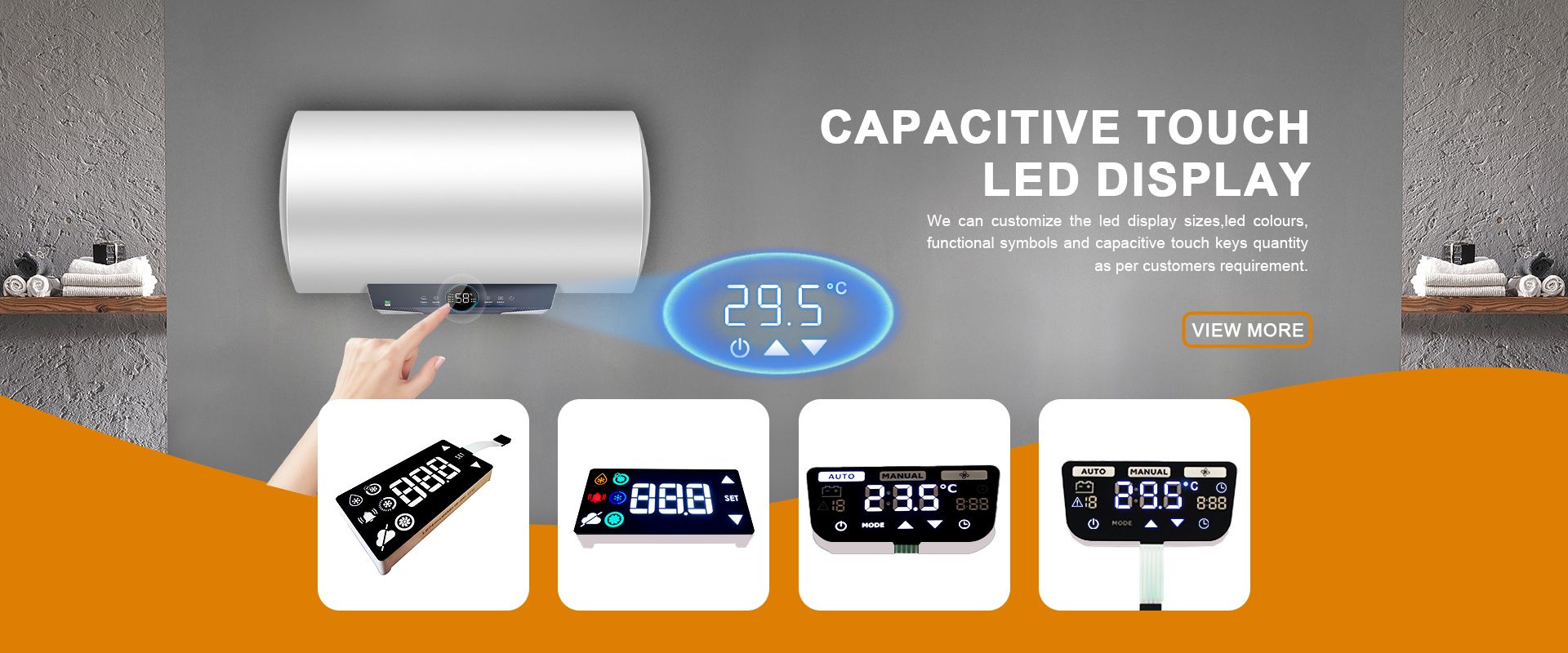
TM1637 vs HT16K33 vs MAX7219: Choosing a Driver IC for Custom LED Displays
Time : Oct 22, 2026 View : 510
A single driver IC for a segment display can be very handy in reducing the number of wires connected to the MCU to as few as 2-3 control lines, instead of using a much larger parallel interface. Of course there are many such driver ICs available in the market. We will concentrate on 3 of the most popular ones, TM1637, HT16K33 and MAX7219. But these 3 ICs behave very differently.
The TM1637 uses two wires for clock and data but has no device address. The HT16K33 uses the I2C interface and supports multiple addresses. The MAX7219 uses a 3-wire serial interface and can be cascaded.
Choosing the wrong chip isn’t just about swapping a single component. It can also mean re-routing traces on the mainboard. The following table gives an overview of the interfaces, number of digits/segments, display layout and expansion possibilities.
Why a Driver IC Changes Your Segment Display Board
A bare multi-digit segment display uses many pins. Typically 8 to 16 pins are directly connected to the corresponding MCU pins. All of these have to be controlled by the MCU, and direct multiplexing can consume MCU time when the display is refreshed in software. Long parallel tracks on the PCB for connecting the display to the MCU can also pick up noise.
The components necessary for the driver IC are moved to the module’s substrate. Such a driver IC multiplexes the information and controls the segment and digit lines locally. The main controller only has to send information on what to display on two to three control lines. On appliance control boards, this also reduces the amount of current-limiting and drive components needed on the main control board.
The benefit of our integrated design concept is also to keep the run length of the high-frequency segment lines short. Such lines, which may be only a few millimeters long, are less exposed to interference than segment lines routed across the entire panel.
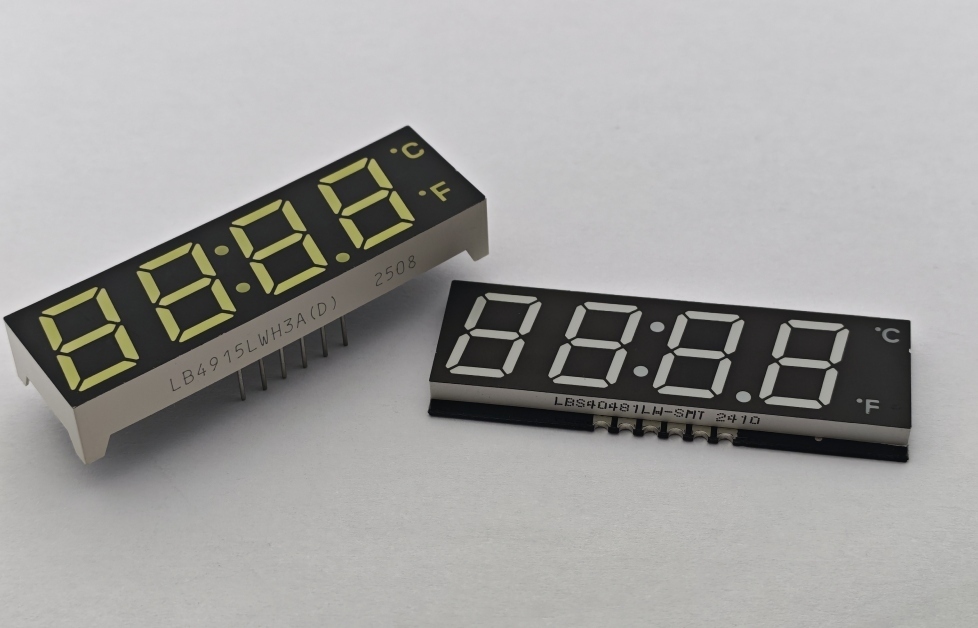
The Three Common Driver ICs at a Glance
These three parts cover many common custom segment display applications. The information above has been rearranged into a table to highlight the relevant information for re-laying out the circuit. Please note that the exact drive current must be cross-checked against the latest data sheet for the part in question.
|
Attribute |
TM1637 |
HT16K33 |
MAX7219 |
|
Interface |
2-wire, CLK/DIO |
2-wire I2C |
3-wire serial |
|
Pins from MCU |
2 |
2 |
3 |
|
Address / chaining |
No device address |
Multiple I2C addresses |
Data-out chain |
|
Display arrangement |
Common-anode output |
ROW/COM matrix |
Common cathode |
|
Typical capacity |
Up to 6 digits |
Up to 16 × 8 LED matrix |
Up to 8 digits |
|
Best fit |
Small numeric readout |
Larger / alphanumeric |
Scalable multi-digit |
The TM1637 and the HT16K33 use 2 wires for control, but are very different in that respect. The TM1637 uses a 2 wire clock and data interface that does not use a device address, so displays need to be independently controlled using separate wires or additional logic to select between them. In contrast, the HT16K33 is an I2C device that can be selected by address, so up to several displays can be connected to the same 2 wires. The MAX7219 uses 3 wires for control, and also has a data-out connection to chain up further devices.
Matching Polarity to the Driver IC
Start by finding out how your display is wired. The TM1637 is typically used with a common-anode display. The MAX7219 chip is typically used with a common-cathode display.
The HT16K33 is a special case, as it is utilizing a ROW/COM matrix. So, it is not a common anode / common cathode driver. Instead, the display wires have to match the IC’s ROW and COM outputs.
Mismatched part pairings often do not produce a fault code but rather a blank or partially illuminated display. Thus, when replacing legacy components with new modules, it is wise to first inspect the wiring and check the polarity of the legacy part. Choose a driver that matches the legacy part and the mainboard logic can then remain mostly unchanged from the original design.
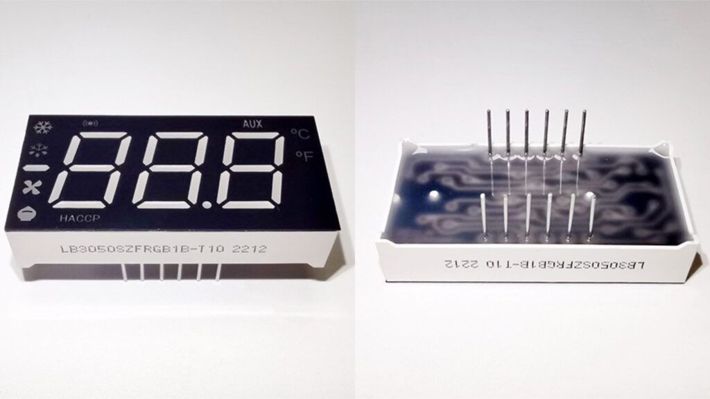
How Many Digits Do You Actually Need
The number of digits in a display of temperature or setpoint typically influences the choice of a particular IC. A simple 2-4 digit display is often sufficient to connect to a small controller using the TM1637. Note that the TM1637 can drive up to 6 digits of display. A larger display, with more segments and more icons, would be driven by the HT16K33 and its larger LED matrix.
Even a single MAX7219 may not be enough to display all the digits you need, but simply adding another one to the chain is enough. Several MAX7219s can be connected to the same clock and load lines. This way, data is distributed from one MAX7219 to the next.
So, in the case of a display that starts with four digits but will later need eight or more, it is very useful to have this headroom. Multiple HT16K33 devices can be connected to the same I2C bus using different addresses.
Noise, Traces, and Noisy Cabinets
The OEMs design display modules to fit their particular environments. Many of these environments contain switching power supplies in the same cabinet as the display. Long, unshielded wires in such an environment can function as antennas. By locating the display driver on the same substrate as the display segments, the length of the wires is minimized and the readout is less exposed to noise from switching supplies located in other parts of the cabinet.
In addition to the display requirements listed above, it is also important to check the temperature for a display that will be used in industrial or outdoor applications. A segment module rated from -40°C to +85°C, driven at 10 to 20 mA per segment, is a common industrial baseline. These figures must be designed into the display using the required operating temperature, maximum LED current, duty cycle and enclosure conditions.
A surface-emitting segment design also holds a ±60° viewing angle and a life above 50,000 hours, which suits equipment that runs continuously for years. Verification of IP67 or other requirements for the finished equipment should be done at the finished equipment, not based on the driver IC.
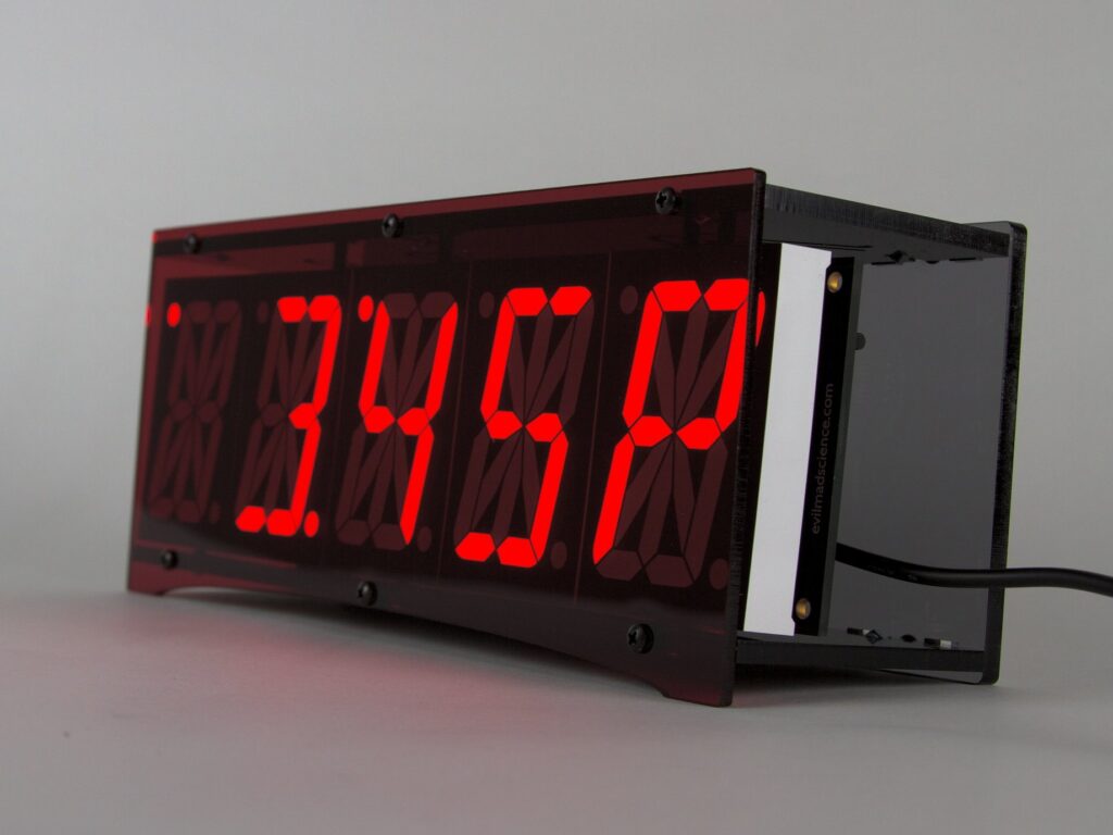
Designing With LIGHTBO
LIGHTBO designs custom segment displays around the chosen driver and the requirements of the existing board. For an existing PCB our in-house design team can create a custom pinout, choose the appropriate display arrangement and select between SMD and through-hole versions to suit your assembly line. The module is available in red, green, yellow, blue, white or amber. Icons, units and other panel features can be chosen as required.
Depending on project requirements, verification can include thermal cycling, burn-in aging, moisture testing and AOI. Applicable materials can be supplied to meet RoHS and REACH requirements. A functional sample can even be created from your CAD drawings while you are still at the schematic design stage for your mainboard.
Conclusion
For simple small numeric readouts with very few pins available, the TM1637 is the easiest solution. For LED modules connected to the same I2C bus, larger matrix or alphanumeric displays using two wires, the HT16K33 offers more flexibility. The MAX7219 is a good solution for common-cathode multi-digit displays. In such cases, several driver ICs may have to be chained together, and the MAX7219 provides a convenient way to manage this.
We would like to know the digit count, display wiring and cabinet dimensions. Based on this information we can narrow down the options for you. It would also be very helpful to see a copy of your schematic. Contact LIGHTBO to send us your panel drawing for review and to request a sample.
FAQ
Q: How many pins does a driver-IC segment display need from the MCU?
Two or three control lines are required to communicate with a display controller. For example, the TM1637 module uses two lines: CLOCK and DATA, whereas the HT16K33 uses the I2C-bus lines SDA and SCL. The MAX7219 display drivers typically need DATA, CLOCK and LOAD signals, so three control lines in total are required.
Q: Can I put two of the same modules on the same two wires?
The answer depends on the driver for the individual displays. The TM1637 display does not have a device address. Thus, independently controlled TM1637 displays normally require separate control lines or additional selection logic. The HT16K33 display has multiple addresses, so several displays can be connected to the same I2C data- and clock lines. Displays based on the MAX7219 can be connected in a chain by connecting the data-out-pin of a display to the data-in-pin of the following display.
Q: Which driver matches a common cathode display?
MAX7219 chips are usually connected to common-cathode displays, TM1637 displays are common-anode, and HT16K33 displays are ROW/COM matrix so you have to check the wiring for the specific display you intend to use and not just choose common-anode or common-cathode.
Q: Does the display survive high-temperature or outdoor service?
That depends on the specifications of the complete display module. The operating temperature, LED current, PCB materials, driver IC and other components all have to meet the requirements of the application. For outdoor use, the display can be incorporated into an appropriately sealed enclosure, but any required IP or NEMA rating should be verified for the finished equipment.


