
Mastering LED Display Module Datasheets: Key Metrics
Time : Jul 23, 2026 View : 340
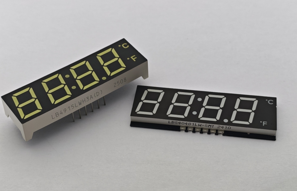
Selecting the right display technology plays a big part in product development. It affects how users interact with the device and how long the product lasts in the field. LIGHTBO stands as a leading high-quality LED display manufacturer. The company has worked for more than twenty years to build strong display solutions. These include advanced 7-segment LED displays, 14 & 16 segment Alphanumeric LED Displays, and Multicolor 10 Segment LED Bars. Such components serve kitchen appliances, industrial instruments, and new energy projects around the world.
When looking at an LED display module, the LED display module datasheet acts as a detailed guide. Reading these papers calls for focus on the numbers that shape actual performance on the job. This guide explains the main LED display module specifications and LED module specifications. It aims to support better choices during purchasing.
Optical Performance Metrics Explained
Optical features decide how well the display shows information in different lighting situations. Here are the main optical LED display specifications to review before settling on a design.
Luminous Intensity and Wavelength
Luminous intensity sets the brightness level of each segment or pixel. Wavelength determines the color that comes out.
- Luminous Intensity (Iv): This figure comes in millicandelas (mcd). It shows the brightness of a segment at a set forward current, often 20mA. LIGHTBO applies high-efficiency chips in items such as our Ultra Bright White 2 Digit 0.56inch 7 Segment SMD LED DISPLAY. These deliver clear views that hold up in bright areas like busy kitchens.
- Peak vs. Dominant Wavelength (λp λd): Peak wavelength marks the main point of light energy released. Dominant wavelength matches the color people actually see. Tight control over these values keeps colors matching from one batch to the next.
Duty Cycle and Multiplexing
Multiplexing and duty cycle control the way a driver sends power to segments. This keeps light steady and avoids flicker.
- Duty Cycle: A number like 1/4 or 1/8 duty tells the portion of time each segment stays powered in one full scan.
- Refresh Rate Requirements: The right duty cycle supports fast scanning. This removes flicker that cameras might catch, or that shows during quick checks.
Electrical Specifications and Thermal Limits
Electrical details in an LED display module datasheet set the safe limits and power use. Getting these wrong may cause early breakdowns or heat buildup.
Forward Voltage and Drive Current
These numbers cover the basic power needs to light the segments safely.
- Forward Voltage (VF): This is the voltage drop across one LED segment when turned on. It changes with color. Red types often sit near 1.8V to 2.0V. Blue and white versions need 3.0V to 3.4V.
- Continuous Forward Current (IF): This marks the highest safe current for ongoing use, commonly 20mA to 25mA. Going over it for long periods cuts brightness and reduces service life.
Power Dissipation and Thermal Management
Handling heat helps preserve color accuracy and protects the module body.
- Maximum Power Dissipation (PD): This figure shows the total power the module can manage at normal room temperature before the internal junction gets too hot.
- Thermal Derating Curves: The curves indicate how much to lower the forward current when surrounding temperatures climb. This matters a lot in hot industrial settings.
|
Metric |
Symbol |
Typical Range (Standard LED) |
Crucial Application Impact |
|
Forward Voltage |
VF |
1.8V – 3.4V (Color dependent) |
Driver IC selection & power consumption tracking |
|
Luminous Intensity |
Iv |
10 mcd – 150+ mcd |
Outdoor readability & display clarity |
|
Peak Wavelength |
λp |
470nm (Blue) – 640nm (Red) |
Brand color consistency & visual matching |
|
Power Dissipation |
PD |
60mW – 100mW per segment |
Lifespan preservation in high-heat environments |
Physical and Environmental Specifications
The build and materials of an LED display module determine its ability to handle bumps, dampness, and chemicals in tough locations.
Package Architecture and Material Selection
How the display is put together affects resistance to wear and outside conditions.
- Epoxy and Plastic Housing: Strong, flame-resistant plastics and special epoxy layers block water entry. They also protect the fine wire connections inside from breaking down.
- Surface Finish and Segment Color: Common choices feature grey or black backgrounds paired with white or clear segments. These combinations improve contrast when the display sits unlit.
Pinout Configurations and Assembly Schemes
Correct pin arrangements and sizes make sure the display fits well on the circuit board.
- Common Anode vs. Common Cathode: Common Anode (CA) links all segment positives to one supply pin. Common Cathode (CC) shares a ground pin. The driver chip must match this setup.
- Mounting Configurations: Through-hole pins (DIP) or SMD LED DISPLAY packages influence assembly speed on the line and how heat moves away.
Bridging Datasheet Metrics to Applications
Picking an LED display module based only on numbers can create problems if the specs do not match the actual surroundings. LIGHTBO works on designs that meet these real demands.
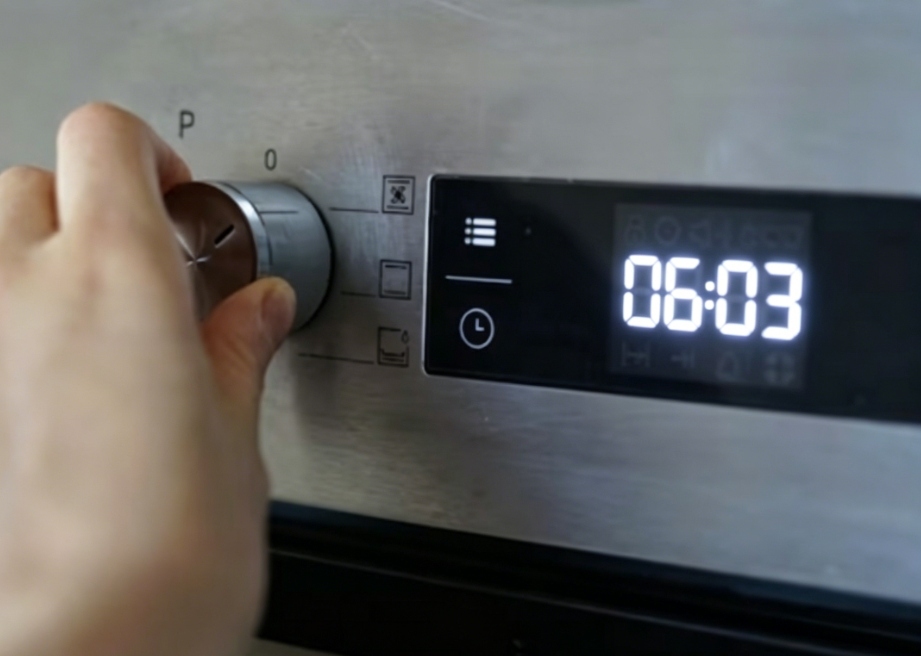
- Kitchen Appliances (Ovens & Refrigerators): Ovens produce high heat that affects ordinary LEDs and leads to dimming or color changes. LIGHTBO applies special heat-resistant epoxy and layout adjustments in products like our Ultra Bright White Custom 7 Segment LED Display For Ovenand our 3 Digit 12.7mm displays for refrigerators. These keep good contrast and steady colors through extended use.
- Industrial Instruments & Power Systems: Variable power supplies and electrical noise may cause flicker or failed segments. Multi-function modules from the company include touch elements and noise reduction features. This supports steady performance on busy factory floors.
- New Energy Charging Stations: Outdoor stations for electric vehicles need displays that resist strong sunlight and wide temperature shifts. LIGHTBO creates bright, stabilized Custom LED Displays. They provide clear reading in daylight and work across a temperature span from -40°C to +85°C.
Why Choose LIGHTBO?
At LIGHTBO, the focus goes beyond basic parts. The company supplies full display solutions.
- Strict Quality Control: ISO 9001 certification, an in-house test lab, and RoHS standards back every batch. Reliability checks help deliver consistent results.
- Advanced Manufacturing & R&D: Automated lines and a design group support custom arrangements, programming, and segment shapes built to fit exact needs.
- Comprehensive Service: Support starts at the drawing stage and continues through production. This approach shortens timelines and cuts integration expenses.
Ready to improve your product’s interface? Contact LIGHTBO Today to talk about your custom needs, ask for official datasheets, or order samples.
FAQ
Q: Why does the luminous intensity of an LED display module drop over time?
A: Heat buildup and currents that run too high speed up wear on the LED chip and the covering material. Good heat control and staying inside the suggested current levels help extend the working life.
Q: What is the difference between Common Anode and Common Cathode configurations in an LED display module datasheet?
A: With Common Anode, all segment positives connect to one supply pin. Segments turn on when their cathodes receive ground. In Common Cathode setups, negatives share a ground pin, and positives get voltage to light individual segments.
Q: How does ambient operating temperature affect LED module specifications?
A: Higher temperatures lower the forward voltage slightly and shift the dominant wavelength a bit. Light output falls, so the display looks dimmer unless the driver accounts for these changes.
Q: Can an LED display module be driven directly by a microcontroller unit (MCU)?
A: Smaller, low-power modules may connect straight to MCU pins. Brighter or multi-digit versions usually need driver chips or extra transistors. Direct connection risks exceeding current limits and can damage ports or create uneven lighting.


