
How Pin Topology Impacts 7-Segment LED Thermal & Driver Choice
Time : Aug 13, 2026 View : 176
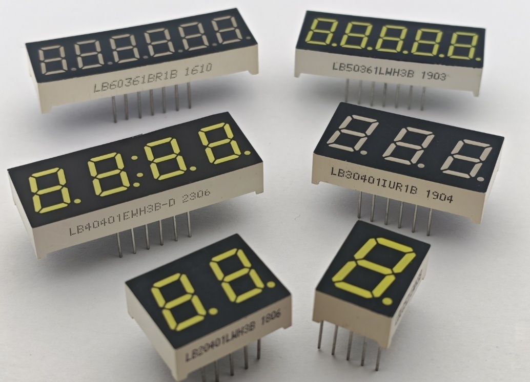
Selecting the right 7-segment LED display involves critical architectural choices that impact circuit efficiency, thermal handling, and board-level design. As a leading custom LED display manufacturer, 7-segment display supplier, and industrial LED display supplier, LIGHTBO specializes in high-reliability 7-segment LED display units, custom LED display modules, and advanced matrix solutions. Established in 2006, as a premier OEM LED display manufacturer, LIGHTBO combines automated production with an internal R&D design team to help global B2B clients optimize digital control interfaces, lower total system costs, and eliminate integration bottlenecks.
Demystifying Display Topology: Common Anode vs Common Cathode
Understanding how internal light-emitting diodes connect to external pins is essential before finalizing any schematic, choosing a specific pin configuration, or selecting active LED driver IC solutions.
The Foundational Circuitry of 7 Segment LED Displays
The basic internal architecture of any numeric display relies on sharing a common pinout to reduce the total connection count.
- Common Anode Display: In a common anode display, all positive anode terminals of the individual LEDs share a single positive power rail (VCC), while each segment (A through G plus the decimal point) is driven individually by connecting its cathode to ground.
- Common Cathode Display: In a common cathode display, all negative cathode terminals share a single ground connection (GND), while individual segment anodes are driven by applying positive voltage to each segment pin.
Why Pin Topology Dictates Microcontroller and Driver Alignment
Microcontroller (MCU) compatibility and output driver stages operate with different current control handling capabilities when sourcing versus sinking electrical current.
- Current Sourcing: The MCU supplies positive current directly out of its GPIO pin to power a common cathode display.
- Current Sinking: The MCU absorbs incoming current through its GPIO pin to ground when switching a common anode display.
Key Differences: Common Anode vs Common Cathode Architecture
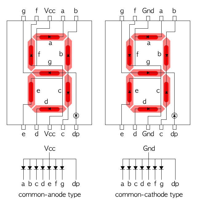
The distinction between these two topologies directly affects power rail configuration, thermal distribution, and switching logic across your PCB layout.
|
Feature / Metric |
Common Anode Display |
Common Cathode Display |
|
Shared Pin Connection |
Positive Voltage Rail (VCC) |
Electrical Ground (GND) |
|
Segment Control Logic |
Active-Low (Logic 0 turns LED ON) |
Active-High (Logic 1 turns LED ON) |
|
Driver Switching Action |
Sinking Current to Ground |
Sourcing Current from Supply |
|
Thermal Concentration |
Distributed across segment drivers |
Concentrated at shared cathode pin |
Driving Logic and Current Control Dynamics
Driving mechanisms and current control strategies must align with your chosen control logic and pin configuration to prevent erratic switching or unintended ghosting.
- Active-Low Switching: Common anode display panels light up when the segment control pin drops to zero volts, making them naturally compatible with open-drain drivers and standard integrated sinking LED driver IC options.
- Active-High Switching: Common cathode display panels turn on when positive voltage is applied, matching PNP transistor arrays or dedicated constant-current sourcing LED driver IC modules.
Thermal Performance and System Efficiency
Proper thermal performance management dictates long-term display brightness stability and prevents accelerated lumen degradation.
- Heat Distribution in Common Anode: Operating in current-sinking mode allows heat to dissipate across multiple separate sinking transistors, keeping localized heat stress on the LED die relatively low for superior overall thermal performance.
- Heat Management in Common Cathode: Because return current flows through a single shared ground line, the common cathode display pin requires wide PCB traces and adequate copper ground pouring to avoid localized thermal build-up and maintain optimal thermal performance.
Multiplexing Efficiency and MCU Pin Optimization
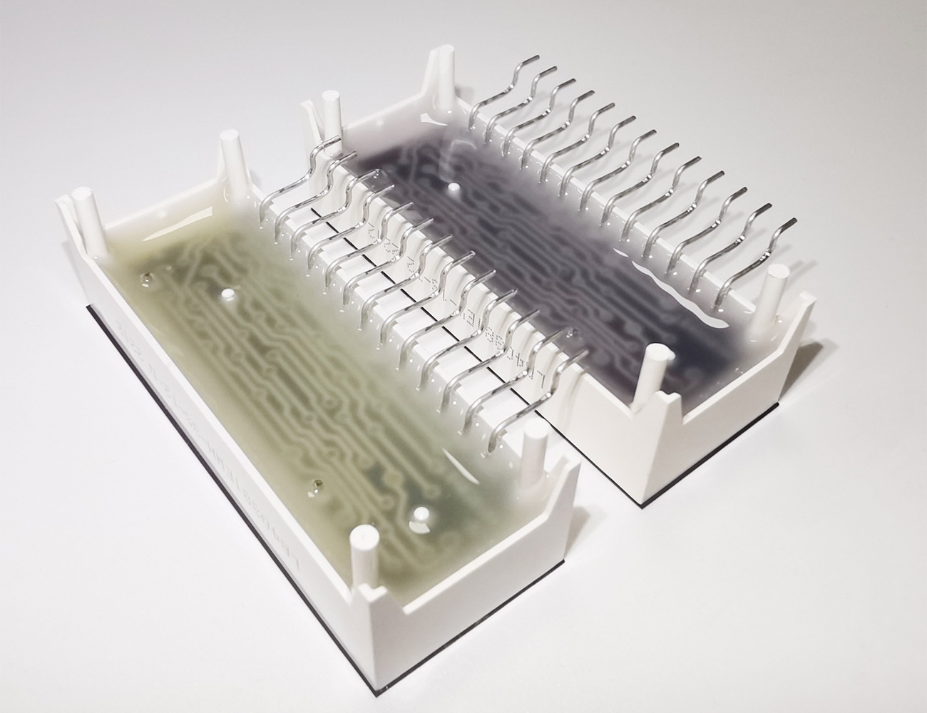
Multi-digit panel designs rely heavily on dynamic multiplexing to reduce microcontroller pin requirements and optimize MCU compatibility.
- Row-Column Matrix Scanning: Rapidly cycling power across shared digit lines via multiplexing allows an MCU to drive multi-digit displays using minimal GPIO lines.
- Strobe-Rate Thermal Relief: High-frequency multiplexing cuts steady-state continuous current consumption, reducing junction heat across high-density display arrays while maintaining seamless MCU compatibility.
Industrial Applications and Practical Display Solutions
Selecting the correct custom LED display configuration ensures high visibility, thermal stability, and operational reliability across demanding deployment environments.
Smart Home Appliances and Consumer Hardware
Modern appliances require clear visual interfaces that withstand ambient operating heat.
- Oven and Range Interfaces: Ultra-bright custom LED display modules equipped with customized common anode display configurations maintain sharp digit contrast even under elevated ambient enclosure temperatures.
- Refrigeration Control Panels: Customized multi-digit 7-segment LED display solutions provide clear temp readouts, utilizing specialized pinout layouts that protect internal drive electronics against moisture intrusion and cold condensation.

Heavy Industrial Equipment and Energy Systems
Industrial environments require stable displays capable of handling continuous operation and heavy electrical loads. As a trusted industrial LED display supplier, LIGHTBO builds robust units for harsh settings.
- New Energy Storage Systems: High-contrast display panels integrate dedicated LED driver IC units to monitor battery voltages, status metrics, and system fault alerts with zero signal latency.
- Power Distribution Instruments: Industrial displays utilize multiplexed common cathode display arrays to reduce overall power consumption while maintaining readable digit outputs on factory floors.
Customized LED Display Solutions from LIGHTBO
As a dedicated custom LED display manufacturer, 7-segment display supplier, and OEM LED display manufacturer, LIGHTBO delivers tailored display engineering backed by strict quality control standards.
Tailored Pinouts and Multiplexed Hardware Layouts
We eliminate engineering compromises by building custom display packages tailored to your specific system architecture.
- Flexible Pin Configurations: We design drop-in replacement displays with custom pinout assignments and specific pin configuration options to match legacy circuit footprints without forcing PCB redesigns.
- Integrated Driver Configurations: We offer custom LED display modules pre-integrated with control LED driver IC chips, reducing active component counts and simplifying MCU compatibility on your primary motherboard.
High-Reliability Manufacturing and Quality Assurance
Our manufacturing processes are structured to deliver long-lasting display performance in demanding operating environments.
- Automated Assembly Lines: Precision SMT lines and automated lead-frame bonding ensure uniform optical alignment and electrical connectivity.
- Rigorous Testing Standards: Every 7-segment LED display batch undergoes thermal shock testing, high-humidity exposure, and automated optical inspection to verify brightness uniformity, thermal performance, and pin configuration integrity.
Are you planning your next hardware release or searching for an experienced industrial LED display supplier and custom LED display manufacturer? Contact LIGHTBO today to discuss your custom LED display specifications, request engineering samples, or receive a fast quote from our technical design team.
FAQ
Q: Can a common anode display be directly replaced by a common cathode display on an existing PCB?
A: No. Because a common anode display and a common cathode display require opposite control logic (active-low vs. active-high) and reverse polarity pinout configurations, direct swap-outs will short the power rail or prevent segment activation unless driver firmware and board schematics are redesigned.
Q: Which pin configuration is better suited for low-power battery-operated devices?
A: A common cathode display is frequently preferred in low-power systems using modern microcontrollers. Many contemporary MCUs feature more efficient sourcing capabilities or pair directly with dedicated low-power LED driver IC chips optimized for common cathode display scanning and enhanced MCU compatibility.
Q: How does multiplexing impact the brightness and lifespan of a 7-segment LED display?
A: Multiplexing rapidly pulses power to individual digits at rates high enough to avoid visible flicker. While peak current is momentarily increased during active duty cycles to preserve perceived brightness, reduced average power consumption lowers die temperatures, enhances thermal performance, and extends operational lifespan.
Q: What key parameters must be provided when ordering a custom 7-segment LED display from an OEM LED display manufacturer?
A: Buyers should specify digit height, segment color/wavelength, luminous intensity requirements, target operating temperature ranges, multiplexing configuration, active drive logic (common anode display or common cathode display), exact pinout constraints, and LED driver IC or MCU compatibility requirements.


